Page History
| Section | ||||||||||||||||||||||
|---|---|---|---|---|---|---|---|---|---|---|---|---|---|---|---|---|---|---|---|---|---|---|
|
...
Prerequisites
| Tip |
|---|
Assumes the user is familiar with navigating the SBCx000's WebUI |
...
| Note |
|---|
The RBA Feature is included only in SBC version 3.0 or betternewer. |
SBC Configuration
This quick start document shows the steps and interlational parameters required to configure a UX to successfully route calls. The configuration process of a UX should always begin with running a wizard; however, the wizard only needs to be run for the very first configuration.
| Tip |
|---|
There are many different architectures which might be used for connecting remote sites to a main site. The manual pages for this 3G4G feature specify a VLAN switch with the 3G4G and WAN networks sharing a single port of the UX. The implementation below uses a 3G4G router connected to the remote LAN segment, thus dedicating the WAN connection to a SBC port. This configuration elminates then need for a VLAN-capable switch. |
Network Diagram
| Panel | |||||||
|---|---|---|---|---|---|---|---|
| |||||||
|

Before Beginning
As a prerequisite to installing the RBA feature, check the following items:
...
Configure Send STUN Packets to Enabled in the Media | Media System Configuration.
| Panel | |||||||
|---|---|---|---|---|---|---|---|
| |||||||
|

RBA Image
| Tip |
|---|
If your HQ-side SBC was running version 2.2, you will need upgrade both the ASM image as well as the SBC firmware. The latest ASM image is available at support.net.com. |
...
Under the Tasks Tab | Application Solution Module | Reinitialize the pull-down selection will supply the possible images currently available on your ASM. Update your ASM images if you are implementing Lync Server 2013 and there is no Lync 2013 image available on your ASM.
| Panel | |||||||
|---|---|---|---|---|---|---|---|
| |||||||
|

Check the RBA License
Verify that your SBC is licensed for the RBA feature.
| Panel | |||||||
|---|---|---|---|---|---|---|---|
| |||||||
|

DNS Configuration
Add both SBCs to the DNS server. In the example, SBC2000 is the HQ SBC and SBC1000 is the remote network SBC. The DNS server is configured only with the LAN-side IP addresses of these nodes, 10.1.1.74 and 10.1.2.71, respectively.
...
- Remote-network SBC
- HQ SBC
- HQ ASM
- Lync Server

| Panel | |||||||
|---|---|---|---|---|---|---|---|
| |||||||
|
Lync Server Topology Configuration
...
Open the Lync Topology Builder
Start the Topo Builder
Panel borderStyle none Caption 0 Figure 1 Start Topology Builder 
Enter Login Credentials
Panel borderStyle none Caption 0 Figure 1 Login Credentials 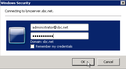
Download the Topology
Panel borderStyle none Caption 0 Figure 1 Download Topology 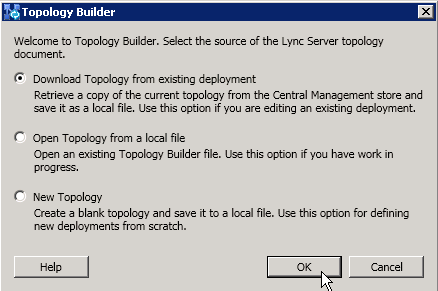
Specify a Filename
Panel 
Confirm ChangesborderStyle none 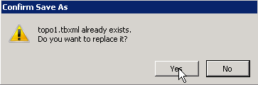
Caption
New Branch Site
0 Figure 1 Specify Filename Confirm Changes
Panel borderStyle none Caption 0 Figure 1 Confirm
New Branch Site
Add Add a new Branch Site. In the example, Taveuni is the new remote branch.
Right-click on Branch Sites and select New Branch Site
Panel borderStyle none Caption 0 Figure 1 New Branch Site 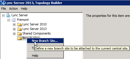
Enter the remote site identity
Panel borderStyle none Caption 0 Figure 1 Remote Site Identity 
Configure the site details
Panel borderStyle 
none
New PSTN Gateway
Caption 0 Figure 1 Site Details
New PSTN Gateway
Add sbc1000.Add sbc1000.sbc.net as Taveuni's PSTN Gateway.
| Panel | |||||||
|---|---|---|---|---|---|---|---|
| |||||||
|

| Panel | |||||||
|---|---|---|---|---|---|---|---|
| |||||||
|

| Panel | |||||||
|---|---|---|---|---|---|---|---|
| |||||||
|

| Panel | |||||||
|---|---|---|---|---|---|---|---|
| |||||||
|

| Info |
|---|
The RBA function requires media bypass, which, in turn requires TLS/SRTP. Later this document, the remote PSTN gateway will be re-configured from TCP/RTP to TLS/SRTP. Employing the simplier TCP/RTP model will help ease the implementation by providing a phased approach to the implementation. |
...
Finally, Publish the newly configured topology.
| Panel | |||||||
|---|---|---|---|---|---|---|---|
| |||||||
|

| Panel | |||||||
|---|---|---|---|---|---|---|---|
| |||||||
|

Lync Server Configuration
Create a new Site Voice Policy
Click New
Panel borderStyle none Caption 0 Figure 1 New 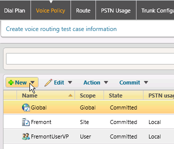
Add a Site Policy
Panel borderStyle none Caption 0 Figure 1 Add Site Policy 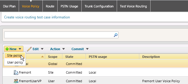
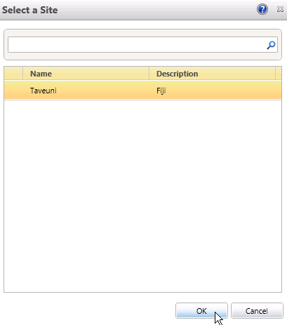
Select the remote site you just added to the Lync topology.
Add a new PSTN Usage

Panel borderStyle none Caption 0 Figure 1 Select Remote Site Add a new PSTN Usage
Panel borderStyle none Caption 0 Figure 1 Add PSTN Usage Supply Supply a Name and Add a Route
Panel borderStyle none Caption 0 Figure 1 Name and Route 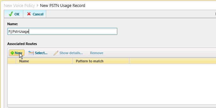
Configure a call route pattern
Panel borderStyle none Caption 0 Figure 1 Configure Call Route Pattern 
Add a Trunk
Panel borderStyle none Caption 0 Figure 1 Add Trunk 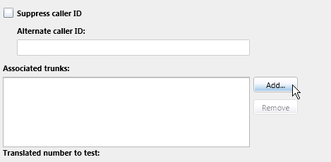
Choose the newly added remote-network SBC
Panel borderStyle none Caption 0 Figure 1 Select Trunk 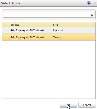
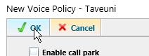
Click OKat each of the configuration layers
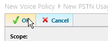
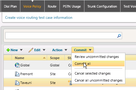
Commit New Site Voice Policy
Commit the changes to the Voice Policy
Click the Commit pulldown and Commit All
Click OK

Verify Route and PSTN Usage
Panel borderStyle none Caption 0 Figure 1 Configuration Level 1 Panel borderStyle none Caption 0 Figure 1 Configuration Level 2 Panel borderStyle none Caption 0 Figure 1 Configuration Level 3 Pagebreak
Commit New Site Voice Policy
Commit the changes to the Voice Policy
Click the Commit pulldown and Commit All
Panel borderStyle none Caption 0 Figure 1 Commit All Click OK.
Panel borderStyle none Caption 0 Figure 1 OK Configuration Settings
Verify Route and PSTN Usage
Verify the Route and Verify the Route and PSTN Usages were added properly in the previous steps.
In the top navigation bar, click Route. Ensure that the route was added.
Panel borderStyle none Caption 0 Figure 1 Ensure Route Added 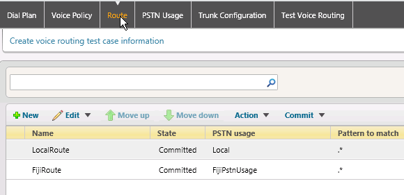
In the top navigation bar, click PSTN Usage. Ensure that the PSTN Usage was added.

Usage. Ensure that the PSTN Usage was added.
Panel borderStyle none Caption 0 Figure 1 Ensure PSTN Usage Added Pagebreak
Create a User New Dial Plan
...
Click Dial Plan in the top navigation. Click New_and select _New User Plan.
Panel borderStyle none Caption 0 Figure 1 New User Dial Plan 
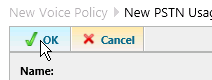
Enter the information for your site and click OK.
Panel borderStyle none Caption 0 Figure 1 OK Information 
Create A New User Voice Policy
...
Click Voice Policy in the top navigation. Click New and select User Policy.
Panel borderStyle none Caption 0 Figure 1 Voice Policy 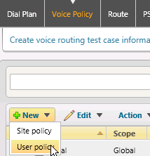
Fill in the form as shown using information for your particular installation.

installation.
Panel borderStyle none Caption 0 Figure 1 Fill in Form Click New under Associated PSTN Usages.
Panel borderStyle none Caption 0 Figure 1 New Associated PSTN Usages 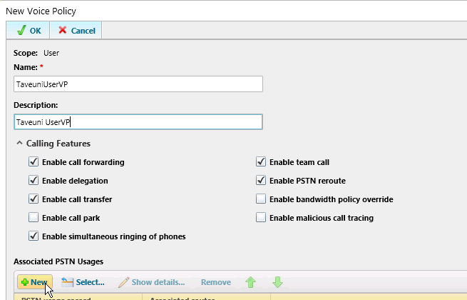
Pagebreak
Create a New PSTN Usage
Create a PSTN Usage to be used with the User-level policies.
Create a New PSTN Usage record.
Panel borderStyle none Caption 0 Figure 1 Create PSTN Usage Record 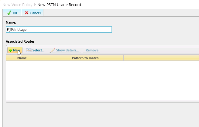
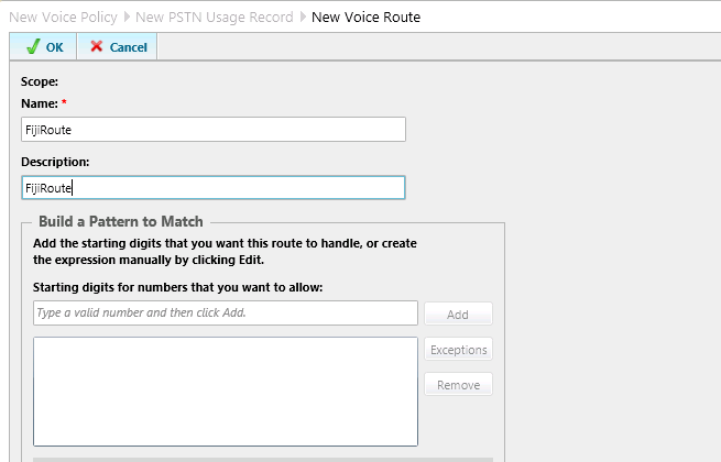
Enter your site-specific configuration information.
Panel borderStyle none Caption 0 Figure 1 Enter Configuration Information Click Add for Associated Trunk
Click Add forPanel borderStyle none Caption 0 Figure 1 Add Associated Trunk 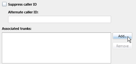
Select the remote-network SBC gateway
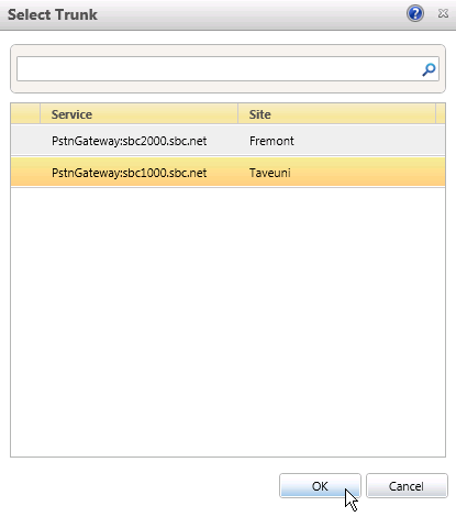
Panel borderStyle none Caption 0 Figure 1 Select Trunk Click OKfor all the configuration layers.
Panel borderStyle none Caption 0 Figure 1 Configuration Level 1 
Pagebreak Panel borderStyle none Caption 0 Figure 1 Configuration Level 2 
Panel borderStyle none Caption 0 Figure 1 Configuration Level 3 
Click OKfor all the configuration layers.
Commit Changes
Commit the additions to your Lync configuration.
Click the Commit pulldown, then select Commit All.
Panel borderStyle none Caption 0 Figure 1 Commit All 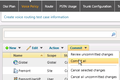
Click OK.
Panel borderStyle none Caption 0 Figure 1 OK Configuration Settings 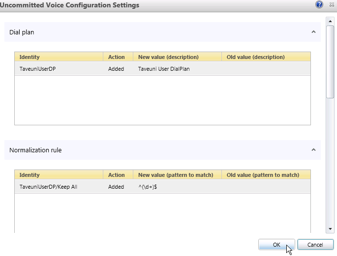
Pagebreak Verify the Route was added.
Panel borderStyle none Caption 0 Figure 1 Verify Route Added 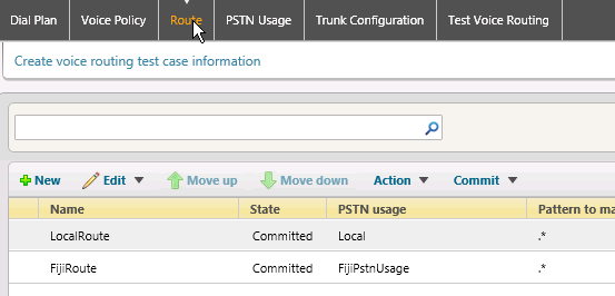
Verify the Route PSTN Usagewas added.
thePanel borderStyle none Caption 0 Figure 1 Verify
was added.PSTN Usage Added 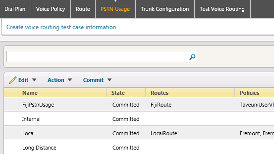
Pagebreak
Add or Move a User into the
...
New Remote Location
You will need to have a user homed to the remote-network location.
Click Users in the left-hand navigation. Enter the name of the user to move to the remote network and click Find.
Panel borderStyle none Caption 0 Figure 1 Find User 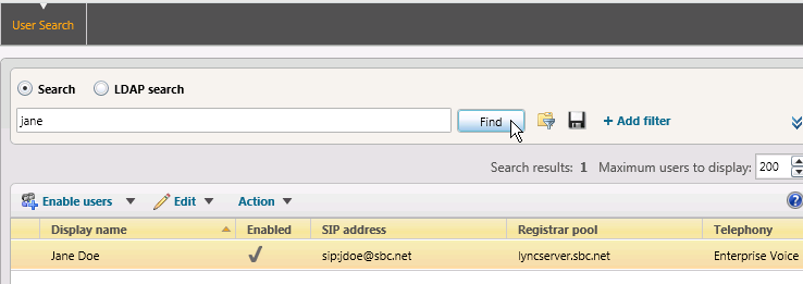
In the Edit pulldown, select Show Details.
Panel borderStyle none Caption 0 Figure 1 Show Details 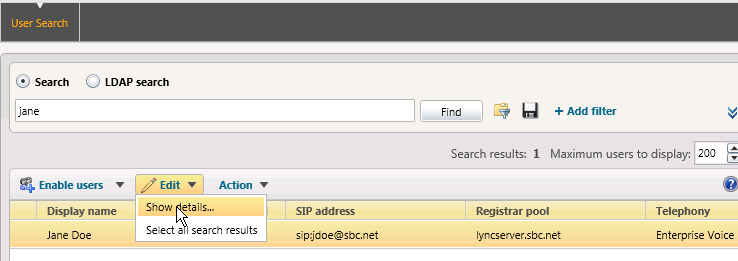
Set the Dial Plan and Voice Policy of the user to thos of the remote network Userpolicies.
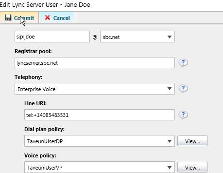
Userpolicies.
Panel borderStyle none Caption 0 Figure 1 Edit Lync Server User Pagebreak
Configure the Network Configuration
...
Click Network Configuration in the left-hand navigation. Click Global in the top navigation, click the Edit pulldown, and select Show Details.
Panel borderStyle none Caption 0 Figure 1 Show Details 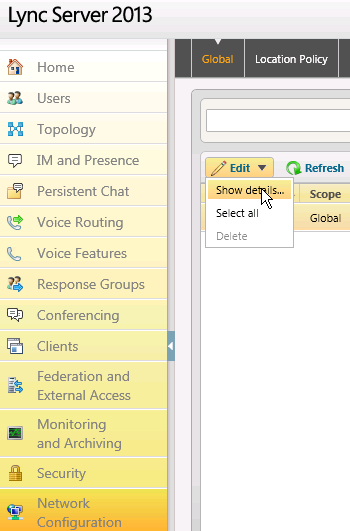
Ensure that the CAC and Bypass options are selected. Change the settings and commit, if necessary.
Panel borderStyle none Caption 0 Figure 1 Edit Global Setting 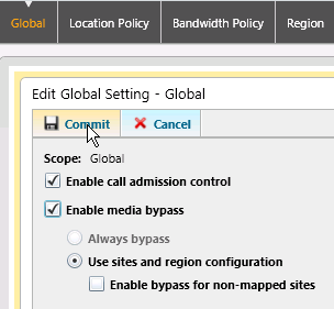
Create a
...
New Bandwidth Policy
Create a Bandwidth Policy to be used to control the CAC from the RBA function.
Click Bandwidth Policy in the top navigation and select New.
Panel borderStyle none Caption 0 Figure 1 New Bandwidth Policy 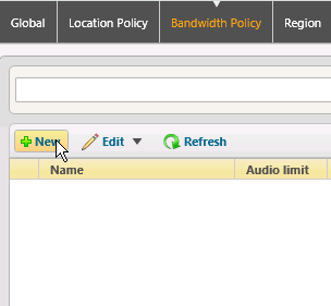
Pagebreak Enter the bandwidth specification for your remote network link, then click Commit.

Panel borderStyle none Caption 0 Figure 1 Enter Bandwidth Specification Pagebreak
Create a
...
New Region
Create regions to be used with the RBA feature. There will be a region for the HQ, as well as the remote-network.
Click Region in the top navigation and select New.
Panel borderStyle none Caption 0 Figure 1 New Region 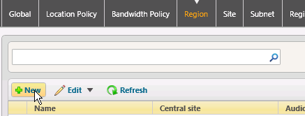
Add a record for the remote region and Commit.
Panel borderStyle none Caption 0 Figure 1 Remote Region Record 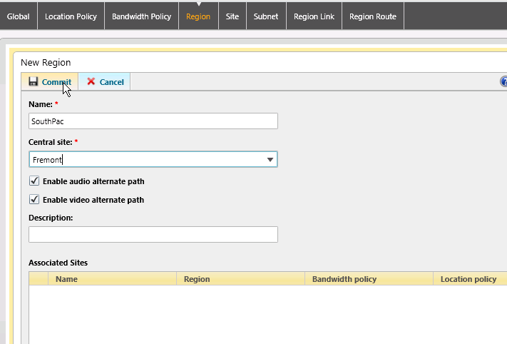
Click New New to add the second region.
Panel borderStyle none Caption 0 Figure 1 Add Second Region 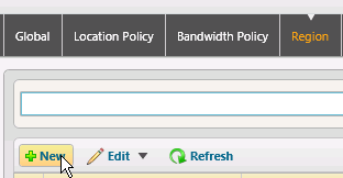
Pagebreak Add a record for the HQ site and Commit.
Panel borderStyle none Caption 0 Figure 1 HQ Site Record 
Add a record for the HQ site and Commit.
Create a new Site
Create sites to be used for the RBA function. Again, there will be a HQ site, as well as a remote site.
Click Site in the top navigation and select New.
Panel borderStyle none Caption 0 Figure 1 New Site 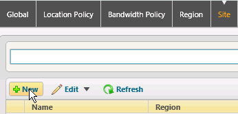
Enter the information for your remote site. Click Commit.
Panel borderStyle none Caption 0 Figure 1 Remote Site Information 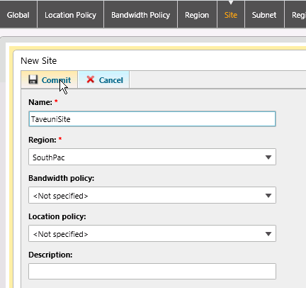
Click New and enter the information for your HQ site. Click Commit.
Panel borderStyle none Caption 0 Figure 1 HQ Site Information 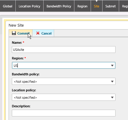
Pagebreak
Create
...
New Subnets
IP addresses are used by the Lync Server to identify the origin of a Lync client. Create subnet records for both the HQ and remote network sites.
Click Subnet in the top navigation and select New.

New.
Panel borderStyle none Caption 0 Figure 1 New Subnet Enter the IP network information for the remote network.
Panel borderStyle none Caption 0 Figure 1 IP Network Information - Remote Network 
Click Newand enter the IP network information for the HQ network.
Panel borderStyle none Caption 0 Figure 1 IP Network Information - HQ Network 
Create a Region Link
Create a Region Link between the sites.
Click Region Link in the top navigation and select New.
Panel borderStyle none Caption 0 Figure 1 New Region Link 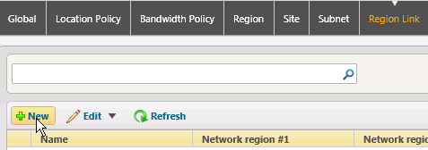
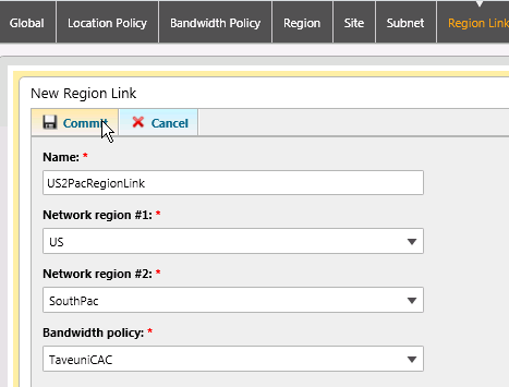
Using the pulldowns, select the HQ Region, the Remote Region and the Bandwidth Policy profile you previously created.
previously created.
Panel borderStyle none Caption 0 Figure 1 Select From Pulldowns Pagebreak
Create a
...
New Region Route
Create a Region Route for the Region Link.
Click Region Route in the top navigation and select New.
Panel borderStyle none Caption 0 Figure 1 New Region Route 
Add the Network Regions as shown and add the newly created Region Link.
Panel borderStyle none Caption 0 Figure 1 Add Network Regions 
Domain Controller Configuration
...
On the Domain Controller, open the Server Manager
Panel borderStyle none Caption 0 Figure 1 Open Server Manager 
Add a new computer to Active Directory. You should have already selected a FQDN for the ASM module during the DNS Configuration section.

section.
Panel borderStyle none Caption 0 Figure 1 Add new Computer Input the name of the ASM computer
Panel borderStyle none Caption 0 Figure 1 Input Name of ASM Computer 
Add the computer to the RTCUniversalServerAdminsgroup

Click OK

RTCUniversalServerAdminsgroup
Panel borderStyle none Caption 0 Figure 1 Add Computer Click OK
Panel borderStyle none Caption 0 Figure 1 OK User or Group Click OK
Panel borderStyle none Caption 0 Figure 1 OK new Object 
Click OK
Configuring the RBA
| Tip |
|---|
Have you added the RBA as a computer in the Domain Controller and made it part of the RTCUniversalServerAdmins group? |
Verify the ASM Board is Available using the Tasks Tab | Operational Statusselection
Panel borderStyle none Caption 0 Figure 1 Verify ASM Board 
Click Setup SBA in the left-hand navigation
Panel borderStyle none Caption 0 Figure 1 Setup SBA 
Click the ASM Config Tab and supply the information for your ASM. Click Apply.
Panel borderStyle none Caption 0 Figure 1 Apply ASM Information 
Click the Domain tab and supply the domain information for your network. Click OK. It will take a minutes to add the ASM to the domain and reboot.

the domain and reboot.
Panel borderStyle none Caption 0 Figure 1 Domain Tab The Current Activity Panel will show when the domain join and rebooting processes are complete
Panel borderStyle none Caption 0 Figure 1 Current Activity Panel 
Click the Deploy SBA tab and select Prepare SBA. This will install the necessary components for the ASM to process the CAC changes supplied by the remote-network SBC. It will take approximately 30 minutes for the installation to complete.
Panel borderStyle none Caption 0 Figure 1 Prepare SBA 
| Info |
|---|
The RBA requires only the Prep SBA step. The other SBA deployment steps are not required. |
...
Ensuring the WAN and IPsec traffic use the appropriate routes is crucial to successful RBA failover.
SBC 1000 Static Routes
Click the Settings Tab and select Static Routes as shown in the diagram
Panel borderStyle none Caption 0 Figure 1 Static Routes 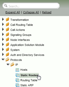
On the remote-network SBC, add a Static IP Route
Panel borderStyle none Caption 0 Figure 1 Add Static IP Route 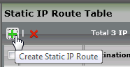
Create a default route that points to the WAN interface on the HQ SBC. Set the Metric to 1.
Panel borderStyle none Caption 0 Figure 1 Create Default Route - Metric 1 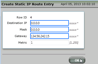
Create another default route that points to the IPSec IPsec interface on the HQ SBC. Set the Metric to 2.
Tip Default routes are required for the automated routing failover to function. Only use default routes.
Panel borderStyle none Caption 0 Figure 1 Create Default Route - Metric 2 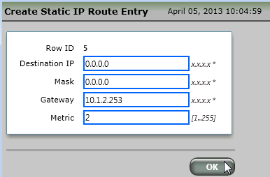
Verify the newly added static routes
Panel borderStyle none Caption 0 Figure 1 Verify Static Routes 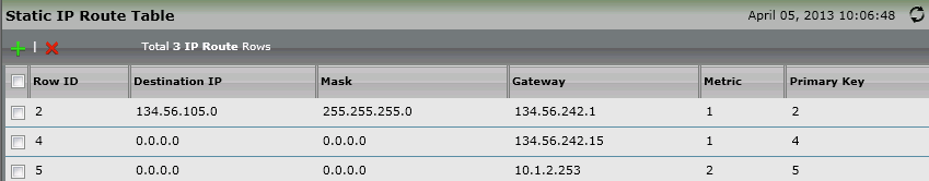
SBC 2000 Static Routes
On the HQ SBC, add specific subnet routes that point to the remote-network. One route should use the remote-network SBC's WAN connection (metric 1), the other should point to the Internet gateway (metric 2).
- When the WAN is up, the WAN-specific route to the remote-network will be used.
- When the WAN is down, the default Internet router will be used to send the traffic via the 3G4G carrier network.network.
| Panel | |||||||
|---|---|---|---|---|---|---|---|
| |||||||
|

SIP Server Tables and Signaling Groups
...
Click SIP Server Tablesin the left-hand navigation
Panel borderStyle none Caption 0 Figure 1 SIP Server Tables 
Add a SIP Server Table
Panel borderStyle none Caption 0 Figure 1 Add SIP Server Table 
Enter a description and click Apply.

Panel borderStyle none Caption 0 Figure 1 Apply Description Click the newly added SIP Server Table
Click the newly addedPanel borderStyle none Caption 0 Figure 1 Click New SIP Server Table Enter the information for the HQ SBC
Panel borderStyle none Caption 0 Figure 1 HQ SBC Information 
SBC 1000 Signaling Groups
Click Signaling Groupsin the left-hand navigation. Add a Signaling Group for the HQ SBC.
Panel borderStyle none Caption 0 Figure 1 Signaling Groups 
Add the information to the newly added SG.
Panel borderStyle none Caption 0 Figure 1 Add SG Information 
SBC 2000 SIP Server Table
On the HQ SBC, add a SIP Server Table that points to the remote-network SBC

SBC
Panel borderStyle none Caption 0 Figure 1 Add SIP Server Table
SCB 2000 Signaling Groups
On the HQ SBC, add a Signaling Group that points to the remote-network SBC
Panel borderStyle none Caption 0 Figure 1 Add Signaling Group 
On both SBCs, ensure that the Signaling Groups come Up
Panel borderStyle none Caption 0 Figure 1 Ensure Signaling Groups Come Up - SBC 1000 
Panel borderStyle none Caption 0 Figure 1 Ensure Signaling Groups Come Up - SBC 2000 
Verification
Verifying Routing
On the HQ SBC, verify that the Routing Table shows the route to the remote network using the WAN IP address of the remote SBC. In this case, the route to 10.1.2.0 (remote network) uses the remote SBC's 134.56.242.16 as the gateway..
| Panel | |||||||
|---|---|---|---|---|---|---|---|
| |||||||
|

Testing Connectivity over the WAN Link
...
At this point you should be able to call Lync-to-Lync over the WAN.
Creating the
...
IPsec Tunnel
Use the following steps to configure an IPsec tunnel between the remote and HQ SBCs.
SBC1000
...
IPsec Configuration
The following steps configure the remote SBC to generate an IPsec tunnel to the HQ SBC when the WAN is down.
Click IPSec IPsec | Tunnel Tablein the left-hand navigation.
Panel borderStyle none Caption 0 Figure 1 Tunnel Table 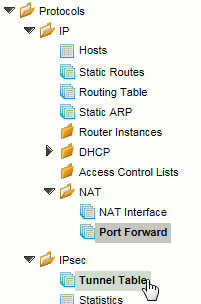
Add a Tunnel Table
Panel borderStyle none Caption 0 Figure 1 Add Tunnel Table 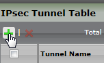
- Enter the configuraton information for your IPsec tunnel.
- The Local Subnet Address must be programmed with IP information for the remote network.
The Remote Subnet Addressmust be programmed with IP information for the HQ network.
Panel borderStyle none Caption 0 Figure 1 Enter Configuration Information 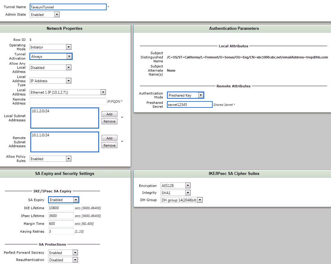
SBC2000
...
IPsec Tunnel Configuration
The following steps configure the HQ SBC to receive an IPsec tunnel from the remote SBC when the WAN is down.
Configure an IPsec tunnel on the HQ SBC with information appropriate to your network. On the HQ SBC, the Local Subnet Address is the HQ network, the Remote Subnet Addressis the remote network subnet(s).

subnet(s).
Panel borderStyle none Caption 0 Figure 1 Create IPsec Tunnel Entry
Verification
In this section you will test the IPsec tunnel to ensure connectivity exists when the WAN link is down.
...
- Pull the cable from the WAN port on the Remote SBC. You must pull the cable from the WAN port on the Remote SBC for this verification step. Downing the WAN port results in automatically disabling the WAN IP route.
Manually remove the WAN Route from the HQ SBC
Panel borderStyle none Caption 0 Figure 1 Remove WAN Route 
On the Remote SBC, use the refresh button to verify the Service Status is Link Up.
Panel borderStyle none Caption 0 Figure 1 Verify Service Status 
The Signaling Groups should come back up after the IPsec tunnel is esablished.
.
Panel borderStyle none Caption 0 Figure 1 Signaling Groups - SBC 1000 Panel borderStyle none Caption 0 Figure 1 Signaling Groups - SBC 2000
Verifying PC Connectivity
...
Before proceeding, replace the HQ SBC WAN route to the remote SBC.
| Panel | |||||||
|---|---|---|---|---|---|---|---|
| |||||||
|

Configuring for Automated Switchover
With the successful testing of the static IPsec tunnel, it is time to make the tunnel dynamic so that the 3G4G link is only used activated when the WAN is down.
Modify the Remote SBC IPSec IPsec Tunnel Activation to Link Monitor Action and click OK.
Panel borderStyle none Caption 0 Figure 1 Modify Tunnel Activation 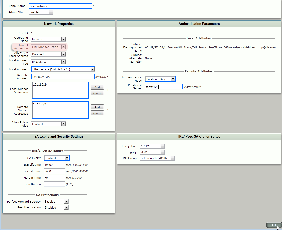
SBC 1000 CAC Profiles
The CAC profiles are transmitted to the Lync Server via the HQ SBC when the WAN transitions link states.
...
Click WAN in the left-hand navigation and select CAC Profiles.
Panel borderStyle none Caption 0 Figure 1 CAC Profiles 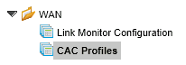
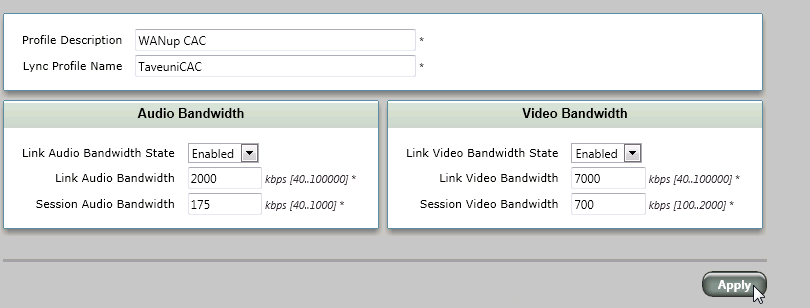
Create a profile for the WAN up situation. Set the bandwidths according to your desired WAN link configuration and capacity. Click Applywhen finished.
.
Panel borderStyle none Caption 0 Figure 1 Create Profile for WAN Up Now, create a CAC profile for WAN down. Setting the Bandwidth State to Disabledresults in any HQ<>remote-network calls being routed over the PSTN.
Panel borderStyle none Caption 0 Figure 1 Create CAC Profile for WAN Down 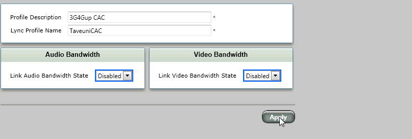
SBC 1000 Link Monitor Configuration
The Link Monitors provide the ability for the remote SBC to know whether the WAN is up and available.'
Click Link Monitor Configuration
Panel borderStyle none Caption 0 Figure 1 Link Monitor Configuration 
Add a monitor to monitor the public IP interface of the HQ SBC and click Apply.
Panel borderStyle none Caption 0 Figure 1 Monitor Public IP Interface 
Add a monitor to monitor the 3G4G router port. Associate this Link Monitor with the IPsec Tunnel you recently created. With this link activated (due to WAN down), the IPsec tunnel will be automatically started.

tunnel will be automatically started.
Panel borderStyle none Caption 0 Figure 1 Monitor 3G4G Router Port
Verification
Verify the following tables on the remote SBC
| Panel | |||||||
|---|---|---|---|---|---|---|---|
| |||||||
|

| Panel | |||||||
|---|---|---|---|---|---|---|---|
| |||||||
|

SBC 2000 Link Monitor Configuration
...
Create a fake CAC entry. This entry will be ignored for purposes of bandwidth adjustment.
Panel borderStyle none Caption 0 Figure 1 Create Fake CAC Entry 
Create a Link Monitor that monitors the WAN interface of the remote SBC.

remote SBC.
Panel borderStyle none Caption 0 Figure 1 Create Link Monitor
Verification
Verify the condition of the routes and IPsec links.
...
With the WAN link up, the HQ SBC routing table and Link Monitor should resemble the following.
| Panel | |||||||
|---|---|---|---|---|---|---|---|
| |||||||
|

| Panel | |||||||
|---|---|---|---|---|---|---|---|
| |||||||
|

Remote SBC
With the WAN link up, the remote SBC's routing table should point to the WAN interface on the HQ SBC.
Panel borderStyle none Caption 0 Figure 1 Routing Table - Point to WAN Interface 
The Link Monitor Table should be Readyon the WAN link

WAN link
Panel borderStyle none Caption 0 Figure 1 Link Monitor Table - Ready The IPsec tunnel should be Link Down
Panel borderStyle none Caption 0 Figure 1 IPsec Tunnel - Link Down 
Lync Server
Verify the Lync Bandwidth Profile using the Bandwidth Policy Service Monitor, which is installed as a component of the optional Lync Server Resource Kit (available from the Microsoft Lync Server website).
Open Windows Explorer to C:\Program Files\Microsoft Lync Server 2013\ResKit\BandwidthPolicyServiceMonitor and select PDPMonUI.exe.
Panel borderStyle none Caption 0 Figure 1 Select PDPMonUI.exe 
Expand the server name in the left-hand navigation and select the expanded server.

and select the expanded server.
Panel borderStyle none Caption 0 Figure 1 Expanded Server Name Click the Topology Infotab
Click thePanel borderStyle none Caption 0 Figure 1 Topology Info tab 
Verify the bandwidth settings are for the WAN up values.
Panel borderStyle none Caption 0 Figure 1 Verify Bandwidth Settings 
Lync Clients
Test a call between a HQ and Remote Lync client. Calls between HQ and Lync clients should connect directly over the WAN without need for a PSTN connection.
...
Downing the WAN Link should result in the following status. With the WAN link down, verify your implementation to the following:
HQ SBC Status
On the HQ SBC, the WAN Link Monitor should show down and the IPsec tunnel up.
Panel borderStyle none Caption 0 Figure 1 Link Monitor Service Status
...

Panel borderStyle none Caption 0 Figure 1 IPsec Tunnel Service Status 
On the HQ SBC, the WAN Link Monitor should show down and the IPsec tunnel up.
Remote SBC Status
On the Remote SBC, the Link Monitor should show the 3G4G link up, the WAN link down, and the IPsec tunnel up.
| Panel | |||||||
|---|---|---|---|---|---|---|---|
| |||||||
|

| Panel | |||||||
|---|---|---|---|---|---|---|---|
| |||||||
|
Lync Server
Within two or three minutes, the Bandwidth Policy should automatically update to the Bandwidth Policy should automatically update to the WAN down bandwidth values.
...
WAN down bandwidth values.
| Panel | |||||||
|---|---|---|---|---|---|---|---|
| |||||||
|

Lync Clients
Test a call between a HQ and Remote Lync client. In the WAN down condition, you should be able to call between HQ and Remote Lync clients. The calls should utilize the PSTN connection between the SBCs.
...
On the Lync Server, start the Topology Builder and Edit Properties for the remote site Trunk.
Panel borderStyle none Caption 0 Figure 1 Edit Properties 
Change the port and configuration to support TLS as shown.
Panel borderStyle none Caption 0 Figure 1 Change Port and Configuration 
Publish the topology.
Panel borderStyle none Caption 0 Figure 1 Publish Topology 
Certificate for the SBC
Certificates are required for TLS/SRTP functionality. The following steps will assist you in installing certificates on the remote SBC.
Click the Taskstab.

.
Panel borderStyle none Caption 0 Figure 1 Tasks Tab Click Lync Setupin the left-hand navigation
Panel borderStyle none Caption 0 Figure 1 Lync Setup 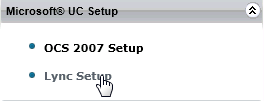
Obatin the root certificate from your network administrator and copy it to your PC. From the webui, click Import Trusted CA Certificateas shown.
Panel borderStyle none Caption 0 Figure 1 Import Trusted CA Certificate 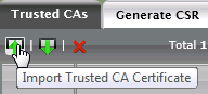
Set the Mode to File Upload and Browseto find the file containing the root certificate.
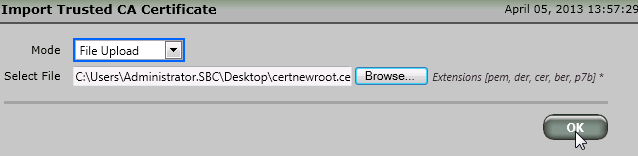
the root certificate.
Panel borderStyle none Caption 0 Figure 1 CA Certificate File Upload Click OKto import the root certificate.
Panel borderStyle none Caption 0 Figure 1 Import Root Certificate 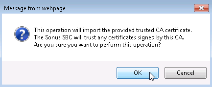
Click OKto import the root certificate.
Click the Generate CSRto generate a certificate request for the SBC. You will send this certificate request to be signed by the your certificae authority.
Panel borderStyle none Caption 0 Figure 1 Generate CSR 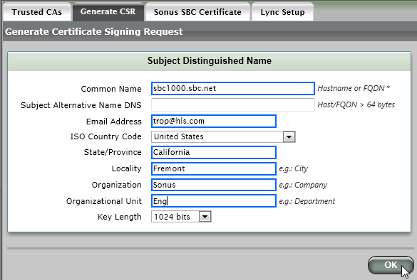
Copy and paste the certificate request into a file and send it to your root certificate authority for signing.
Panel borderStyle none Caption 0 Figure 1 Result 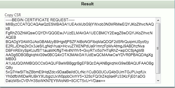
When the signed certificate is returned, click the Sonus SBC Certificatetab and import the certificate.
Panel borderStyle none Caption 0 Figure 1 Import Certificate 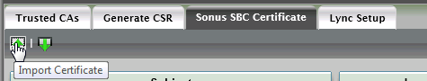
Set the Mode to File Upload and Browseto find the file containing the SBC certificate.

the SBC certificate.
Panel borderStyle none Caption 0 Figure 1 SBC Server Certificate File Upload Verify the SBC and root certificates
Panel borderStyle none Caption 0 Figure 1 Sonus SBC Certificate 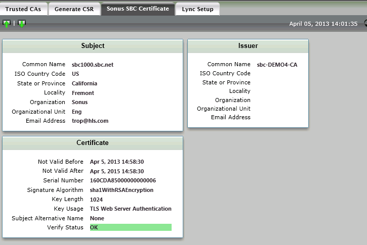
Panel borderStyle none Caption 0 Figure 1 Trusted CAs 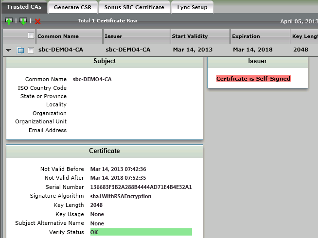
Setting the SIP Server and Signaling Group for TLS/SRTP
On the remote SBC, set/create the Lync Server SIP Server as shown.
Panel borderStyle none Caption 0 Figure 1 Set/Create Lync Server SIP Server 
Set/create a Lync Server Signaling Group as shown.
Panel borderStyle none Caption 0 Figure 1 SIP Signaling Group Details 
The Lync Server Signaling Group should come up
Panel borderStyle none Caption 0 Figure 1 Lync Server Signaling Group - Up 
RBA Data Flows
WAN Up Flow
|

WAN Down Instant Message Flow
|

WAN Up Flow
| Panel | |||||||
|---|---|---|---|---|---|---|---|
| |||||||
|
WAN Down Instant Message Flow
| Panel | |||||||
|---|---|---|---|---|---|---|---|
| |||||||
|
WAN Down Lync-to-Lync Call Flow
| Panel | |||||
|---|---|---|---|---|---|
| |||||
|
...
|

- As an IP router, the SBC forwards the SIP request from the remote Lync to the Lync Server
- Lync server sends a SIP request to the remote SBC (as a SIP --> PSTN gateway)
- Remote SBC dials the HQ SBC via PSTN
- HQ SBC (as a SIP Gateway) sends a SIP request to the Lync server
- Lync Server sends SIP Request to the HQ Lync client
- Remote Lync client audio bypasses directly to the remote SBC.
...
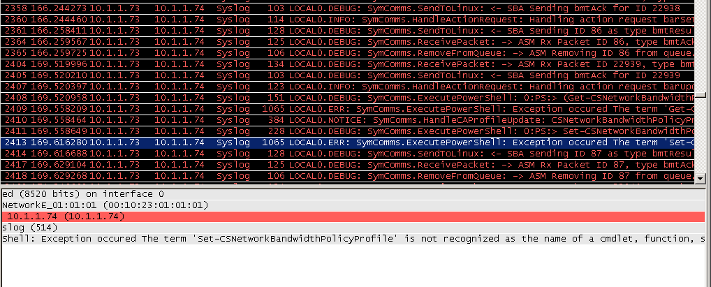
A wireshark trace which shows an exception due to an unrecognized cmdlet is likely due to the Prep SBA function not being executed. Review the Configuring the RBA section of this document.
| Panel | |||||||
|---|---|---|---|---|---|---|---|
| |||||||
|
RBA computer not a member of RTCUniversalServerAdmins group
...
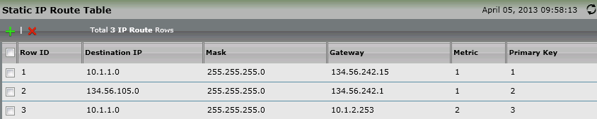
Check the routing table on the remote SBC. The remote SBC must use default routes (0.0.0.0/0) rather than network routes.
| Panel | |||||||
|---|---|---|---|---|---|---|---|
| |||||||
|

...
| Panel | |||||
|---|---|---|---|---|---|
| |||||
|
...
|
...
|
OPTIONS with Carrier's IP address
...
This wireshark trace shows a properly working cmdlet to change the CAC bandwidth policies.
| Panel | |||||||
|---|---|---|---|---|---|---|---|
| |||||||
|

rev 0.2
Overview
Content Tools