

Table of Contents
Interoperable Vendors

Copyright
© 2021 Ribbon Communications Operating Company, Inc. © 2021 ECI Telecom Ltd. All rights reserved. The compilation (meaning the collection, arrangement and assembly) of all content on this site is protected by U.S. and international copyright laws and treaty provisions and may not be used, copied, reproduced, modified, published, uploaded, posted, transmitted or distributed in any way, without prior written consent of Ribbon Communications Inc.
The trademarks, logos, service marks, trade names, and trade dress (“look and feel”) on this website, including without limitation the RIBBON and RIBBON logo marks, are protected by applicable US and foreign trademark rights and other proprietary rights and are the property of Ribbon Communications Operating Company, Inc. or its affiliates. Any third-party trademarks, logos, service marks, trade names and trade dress may be the property of their respective owners. Any uses of the trademarks, logos, service marks, trade names, and trade dress without the prior written consent of Ribbon Communications Operating Company, Inc., its affiliates, or the third parties that own the proprietary rights, are expressly prohibited.
Document Overview
This document outlines the configuration best practices for the Ribbon SBC Core (SBC 5K, 7K, SWe) when deployed with Zoom Bring Your Own Carrier (BYOC). This means that for all subscribers catering to Zoom customers, the PSTN calls terminating through the local SBC Core are directly connected to the Service Provider of their choice.
A Session Border Controller (SBC) is a network element deployed to protect SIP-based Voice over Internet Protocol (VoIP) networks. Early deployments of SBCs were focused on the borders between two service provider networks in a peering environment. This role has now expanded to include significant deployments between a service provider's access network and a backbone network to provide service to residential and/or enterprise customers. The interoperability compliance testing focuses on verifying inbound and outbound call flows between Ribbon SBC 5K/7K/SWe and Zoom cloud. Ribbon SBC 5K/7K/SWe is deployed on the customer site to resolve any potential numbering format issue between Zoom and the customer's existing carrier dial plan numbering.
This guide contains the following configuration sections:
- Section A: SBC Core Configuration
- Captures general SBC Core configurations for deploying with Zoom BYOC.
- Section B: Configuration for SBC behind NAT
- Captures additional SBC configuration performed behind NAT.
Section C: Zoom Web BYOC configuration
Captures the Zoom BYOC configuration.
Test all basic calls, along with the supplementary features like call hold, call transfer, and conference with configurations from Section A and Section B.
Configure Advanced supplementary features on Zoom as mentioned in Supplementary Services Configuration on Zoom. These include:
Auto Receptionist
Call Flip
Shared Line Appearance (SLA) or Call Delegation
Shared Line Group (SLG)
Note
SBC 5x10, 5400, 7000 and SWe are represented as SBC Core in the following sections.
Non-Goals
It is not the goal of this guide to provide detailed configurations that will meet the requirements of every customer. Use this guide as a starting point and build the SBC configurations in consultation with network design and deployment engineers.
Audience
This is a technical document intended for telecommunications engineers with the purpose of configuring both the Ribbon SBCs and the third-party product.
Steps will require navigating the third-party product as well as the Ribbon product using graphical user interface (GUI) or command line interface (CLI).
Understanding of the basic concepts of TCP/UDP/TLS, IP/Routing, and SIP/RTP/SRTP is needed to complete the configuration and any necessary troubleshooting.
Note
This configuration guide is offered as a convenience to Ribbon customers. The specifications and information regarding the product in this guide are subject to change without notice. All statements, information, and recommendations in this guide are believed to be accurate but are presented without warranty of any kind, express or implied, and are provided “AS IS”. Users must take full responsibility for the application of the specifications and information in this guide.
Pre-Requisites
The following aspects are required before proceeding with the interop:
- Ribbon SBC 5K /7K/SWe Core
- Ribbon PSX (if using external PSX instead of ERE (Embedded Routing Engine)
- Public IP Addresses
- Zoom BYOC (Bring Your Own Carrier) Trunk
- Zoom Go account is required.
- For more details, visit https://go.zoom.us/signin
- TLS Certificates for SBC 5K /7K/SWe Core
- Please refer to TLS Configuration between Ribbon SBC Core and Zoom
Product and Device Details
The following equipment and software were used for the sample configuration provided:
Requirements
Equipment | Software Version | |
|---|---|---|
| Ribbon Communications | Ribbon SBC 5K /7K/SWe Core | V09.00.00R0 |
| Ribbon PSX | V12.02.02R000 | |
| Zoom | Zoom Desktop app | 5.0.5 (26213.0602) |
| Zoom Mobile app | 5.0.5 (26211.0602) | |
Third-party Equipment | Kapanga Softphone | 1.00 |
| Phonerlite | 2.77 | |
| Zoiper | 5.3.8 |
Note
The Ribbon SBC Core portfolio includes SBC 5x10, SBC 5400, SBC 7000 (appliance based), and SBC SWe (virtualized platform). The software version is applicable to Ribbon SBC Core portfolio, and hence, this configuration guide is valid for all these devices.
Network Topology Diagram
This section covers the SBC Core deployment topology and the Interoperability Test Lab Topology.
SBC Core Deployment Topology
SBC Core Deployment Topology

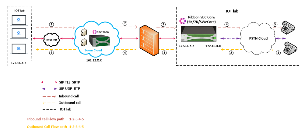
Interoperability Test Lab Topology
The following lab topology diagram shows connectivity between Zoom and Ribbon SBC Core.
Interoperability Test Lab Topology

Section A: SBC Core Configuration
The following SBC Core configurations are included in this section:
- SBC Core can connect to the network as mentioned in Network and Connectivity.
- Zoom prefers transport as TLS. Establishing a TLS connection between SBC Core and Zoom is covered under TLS Configuration between Ribbon SBC Core and Zoom.
- SBC Core specific configuration related to PSTN is covered under PSTN Leg Configuration.
- SBC Core specific configuration related to Zoom is covered under Zoom Leg Configuration.
1. Network and Connectivity
SBC 5400 front and back panel are as shown below:
SBC 5400 Front Panel

SBC 5400 Back Panel

Mgmt - is an RJ45 port and is the management interface of the SBC.
Media 0/1/2/3 depicted as pkt0/pkt1/pkt2/pkt3 are RJ45 ports. Media 0 and Media 1 are used in the current deployment.
2. Static Routes
Static routes are used to create communication to remote networks. In a production environment, static routes are mainly configured for routing from a specific network to a network that can only be accessed through one point or one interface (single path access or default route).
Tip
- For smaller networks with just one or two routes, configuring static routing is preferable. This is often more efficient since a link is not being wasted by exchanging dynamic routing information.
- For networks that have a LAN-side Gateway on Voice VLAN or Multi-Switch Edge Devices (MSEs) with Voice VLAN towards SBC Core, static routing configurations are not required.
Add the static route once PSTN Leg and Zoom Leg configurations are done on the SBC.
Static route towards PSTN
set addressContext default staticRoute 0.0.0.0 0 10.54.X.X LIF1 PKT0_V4 preference 100
commit
Static route towards Zoom
set addressContext default staticRoute 162.12.X.X 24 115.110.X.X LIF2 PKT1_V4 preference 100
commit
3. TLS Configuration between Ribbon SBC Core and Zoom
Prerequisites:
- For TLS to work on the public side of the network, a trusted CA (Certificate Authority) is needed. In this scenario, GoDaddy is used as a Trusted CA.
- Enable Zoom BYOC trunk with TLS/SRTP.
Generate a CSR with OpenSSL
# To create a Certificate Signing Request (CSR) and key file for a Subject Alternative Name (SAN) certificate with multiple subject alternate names, complete the following procedure:

Create an OpenSSL configuration file (text file) on the local computer by editing the fields to the company requirements.

Note 1: In the example used in this article the configuration file is req.conf.

Note 2: req_extensions will put the subject alternative names in a CSR, whereas x509_extensions would be used when creating an actual certificate file.

[req]
        distinguished_name = req_distinguished_name
        req_extensions = v3_req
        prompt = no
        [req_distinguished_name]
        C = US
        ST = VA
        L = SomeCity
        O = MyCompany
        OU = MyDivision
        CN = www.company.com
        [v3_req]
        keyUsage = keyEncipherment, dataEncipherment
        extendedKeyUsage = serverAuth
        subjectAltName = @alt_names
        [alt_names]
        DNS.1 = www.company.com
        DNS.2 = company.com
        DNS.3 = www.company.net
        DNS.4 = company.net

Make sure there are no whitespaces at the end of the lines.

#Run the following commands to create the Certificate Signing Request (CSR) and a new Key file:
openssl req -new -out company_san.csr -newkey rsa:2048 -nodes -sha256 -keyout company_san.key.temp -config req.conf

#Run the following command to verify the Certificate Signing Request:
openssl req -text -noout -verify -in company_san.csr

# After receiving the CSR with above information, provide it to CA (Certificate Authority). You will then receive the proper CA signed certificate in .crt format that is convertable into other formats using openssl.

# By default, you should receive two or more certificates from CA (depanding upon your CA). One is the SBC certificate, and other is CA's root and intermediate certificate.

# Upload the certificates to the SBC at /opt/sonus/external and convert them into SBC-readable format, i.e. SBC certificate is in .pem or .p12 format and root certificate is in .cer or .der.

#Converting .crt to .pem USING OPENSSL for SBC certificate.
openssl x509 -in sbc_cert.crt -out sbc_cert.der -outform DER
openssl x509 -in sbc_cert.der -inform DER -out sbc_cert.pem -outform PEM

#After generating sbc_cert.pem file, convert it to .p12 format using below command and the location of the certificate key.
openssl pkcs12 -export -out sbc1_cert.p12 -in sbc_cert.pem -inkey /opt/sonus/company_san.key.temp

#CONVERTING CRT to CER USING OPENSSL for CA's root and intermediate certificate.
openssl x509 -in root_cert.crt -out root_cert.cer -outform DER

After converting all these certificates upload them on SBC at /opt/sonus/external location.
Generate Required Certificates
#Import Public CA Root Certificate into database.
set system security pki certificate CA_ROOT_CERT type remote fileName root_cert.cer state enabled

#Import Public CA Certified SBC Server Certificate into database.
set system security pki certificate SBC_CERT filename sbc1_cert.p12 passPhrase <Password defined during CSR generation> state enabled type local
TLS Profile
A TLS Profile is required for the TLS handshake between SBC Core and Zoom. This profile defines cipher suites supported by SBC Core. Create the TLS profile as mentioned below:
set profiles security tlsProfile TLS_PROF clientCertName SBC_CERT serverCertName SBC_CERT cipherSuite1 tls_ecdhe_rsa_with_aes_256_cbc_sha384 cipherSuite2 tls_ecdhe_rsa_with_aes_128_cbc_sha authClient true allowedRoles clientandserver acceptableCertValidationErrors invalidPurpose
set profiles security tlsProfile TLS_PROF v1_1 enable
set profiles security tlsProfile TLS_PROF v1_0 disable
set profiles security tlsProfile TLS_PROF v1_2 enable
commit
Attach the TLS Profile to the SIP Signaling Port that will be created later in Zoom Leg Configuration.
set addressContext default zone ZOOM sipSigPort 7 state disabled mode outOfService
commit
set addressContext default zone ZOOM sipSigPort 7 tlsProfileName TLS_PROF
commit
set addressContext default zone ZOOM sipSigPort 7 state enabled mode inService
commit
4. Local Ringback Tone Configuration
This section contains the general SBC configurations.
DSP Resource Allocation
This configuration only applies if the SBC has been deployed with (hardware) DSP resources. If it has not, executing this configuration step has no negative impact. Do not attempt transcoding, so that the lack of compression resources will not impact the overall SBC configuration in this document.
set system mediaProfile compression 75 tone 25
commit
This configuration is not required for SBC SWe 7.2 release onwards.
Local Ringback Tone (LRBT) Profile
Create a Local Ringback Tone (LRBT) profile that is attached to both PSTN and Zoom leg.
Enable Dynamic LRBT.
set profiles media toneAndAnnouncementProfile LRBT_PROF
set profiles media toneAndAnnouncementProfile LRBT_PROF localRingBackTone signalingTonePackageState enable
set profiles media toneAndAnnouncementProfile LRBT_PROF localRingBackTone precedence lower
set profiles media toneAndAnnouncementProfile LRBT_PROF localRingBackTone makeInbandToneAvailable enable
set profiles media toneAndAnnouncementProfile LRBT_PROF localRingBackTone flags useThisLrbtForEgress enable
set profiles media toneAndAnnouncementProfile LRBT_PROF localRingBackTone flags useThisLrbtForIngress enable
set profiles media toneAndAnnouncementProfile LRBT_PROF localRingBackTone flags dynamicLRBT enable
commit
5. PSTN Leg Configuration
Create profiles with a specific set of characteristics corresponding to PSTN. This includes configuration of the following entities on PSTN leg:
- Codec Entry
- Packet Service Profile
- IP Signaling Profile
- IP Interface Group
- Zone
- SIP Signaling Port
- IP Peer
- SIP Trunk Group
- Routing Label
- Call Routing
5.1 Codec Entry
Codec entry allows you to specify the codec used for the call. Create the codec entry for G711Ulaw codec with packet size 20 and rfc2833 method for dtmf.
set profiles media codecEntry G711ULAW codec g711
set profiles media codecEntry G711ULAW law ULaw
set profiles media codecEntry G711ULAW packetSize 20
set profiles media codecEntry G711ULAW dtmf relay rfc2833
commit
5.2 Packet Service Profile (PSP)
Create a Packet Service Profile (PSP) for the PSTN leg. The PSP is attached to sipTrunkGroup created later in this section.
set profiles media packetServiceProfile PSTN_PSP codec codecEntry1 G711ULAW
set profiles media packetServiceProfile PSTN_PSP rtcpOptions rtcp enable
commit
5.3 IP Signaling Profile (IPSP)
Create an IP Signaling Profile with appropriate signaling flags towards PSTN.
set profiles signaling ipSignalingProfile PSTN_IPSP
set profiles signaling ipSignalingProfile PSTN_IPSP egressIpAttributes flags disable2806Compliance enable
commit
5.4 IP Interface Group
Create an IP interface group.
Replace "x.x.x.x" with the SBC's packet interface (pkt) IP address towards PSTN (example pkt0 IP), and "Y" with its prefix length. Provide ceName used during an SBC deployment.
Here the ceName is "ZOOM1".
set addressContext default ipInterfaceGroup LIF1 ipInterface PKT0_V4 ceName ZOOM1 portName pkt0
set addressContext default ipInterfaceGroup LIF1 ipInterface PKT0_V4 ipAddress x.x.x.x prefix Y
set addressContext default ipInterfaceGroup LIF1 ipInterface PKT0_V4 mode inService state enabled
commit
5.5 Zone
Create Zone towards PSTN and specify the id of the zone.
This Zone groups the set of objects used for the communication towards PSTN.
set addressContext default zone PSTN id 2
commit
5.6 SIP Signaling Port
Set the SIP Signaling port, which is a logical address used to send and receive SIP call signaling packets and is permanently bound to a specific zone.
Replace "x.x.x.x" with SIP Signaling Port IP of SBC towards PSTN.
set addressContext default zone PSTN sipSigPort 3 ipInterfaceGroupName LIF1
set addressContext default zone PSTN sipSigPort 3 ipAddressV4 x.x.x.x
set addressContext default zone PSTN sipSigPort 3 portNumber 5060
set addressContext default zone PSTN sipSigPort 3 transportProtocolsAllowed sip-udp
set addressContext default zone PSTN sipSigPort 3 mode inService
set addressContext default zone PSTN sipSigPort 3 state enabled
commit
5.7 IP Peer
Create an IP Peer with the signaling IP address of the PSTN (Service Provider) and assign it to the PSTN Zone.
Replace "x.x.x.x" with the PSTN IP.
set addressContext default zone PSTN ipPeer PSTN_IPP ipAddress x.x.x.x
set addressContext default zone PSTN ipPeer PSTN_IPP ipPort 5060
commit
5.8 SIP Trunk Group
Create a SIP Trunk Group towards the PSTN and assign corresponding profiles like LRBT, PSP, IPSP created in earlier steps.
You must configure Trunk Group names using capital letters.
set addressContext default zone PSTN sipTrunkGroup PSTN_TG media mediaIpInterfaceGroupName LIF1
set addressContext default zone PSTN sipTrunkGroup PSTN_TG mode inService state enabled
commit

set addressContext default zone PSTN sipTrunkGroup PSTN_TG policy signaling ipSignalingProfile PSTN_IPSP
set addressContext default zone PSTN sipTrunkGroup PSTN_TG policy media packetServiceProfile PSTN_PSP
set addressContext default zone PSTN sipTrunkGroup PSTN_TG policy media toneAndAnnouncementProfile LRBT_PROF
set addressContext default zone PSTN sipTrunkGroup PSTN_TG ingressIpPrefix 0.0.0.0 0
commit
5.9 Routing Label
Create a Routing Label with a single Routing Label Route to bind the PSTN Trunk Group with the PSTN IP Peer.
set global callRouting routingLabel PSTN_RL routingLabelRoute 1 trunkGroup PSTN_TG
set global callRouting routingLabel PSTN_RL routingLabelRoute 1 ipPeer PSTN_IPP
set global callRouting routingLabel PSTN_RL routingLabelRoute 1 inService inService
commit
5.10 Call Routing
This entry is used to route all the calls coming from PSTN towards ZOOM endpoints.
Provide ceName used during an SBC deployment. "ZOOM1" is the ceName.
set global callRouting route trunkGroup PSTN_TG ZOOM1 standard Sonus_NULL 1 all all ALL none Sonus_NULL routingLabel ZOOM_RL
commit
6. Zoom Leg Configuration
Create profiles with a specific set of characteristics corresponding to Zoom. This includes configuration of the following entities on Zoom leg:
- Codec Entry
- Packet Service Profile
- IP Signaling Profile
- IP Interface Group
- Zone
- SIP Signaling Port
- IP Peer
- SIP Trunk Group
- Routing Label
- Call Routing
6.1 Codec Entry
Codec entry allows you to specify the codec used for the call. Create the codec entry for G711Ulaw codec with packet size 20 and rfc2833 method for dtmf.
set profiles media codecEntry G711_Zoom codec g711
set profiles media codecEntry G711_Zoom law ULaw
set profiles media codecEntry G711_Zoom packetSize 20
set profiles media codecEntry G711_Zoom dtmf relay rfc2833
commit
6.2 Packet Service Profile (PSP)
Create a Packet Service Profile (PSP) for the Zoom leg. The PSP is attached to the sipTrunkGroup that is created later in this section.
Since there is an SRTP between the SBC Core and Zoom, you must create a crypto suite profile.
set profiles security cryptoSuiteProfile CRYPT_PROF entry 1 cryptoSuite AES-CM-128-HMAC-SHA1-80
The Crypto Suite profile is attached to the ZOOM_PSP.
set profiles media packetServiceProfile ZOOM_PSP codec codecEntry1 G711_Zoom
set profiles media packetServiceProfile ZOOM_PSP rtcpOptions rtcp enable
set profiles media packetServiceProfile ZOOM_PSP secureRtpRtcp cryptoSuiteProfile CRYPT_PROF
set profiles media packetServiceProfile ZOOM_PSP secureRtpRtcp flags allowFallback enable
set profiles media packetServiceProfile ZOOM_PSP secureRtpRtcp flags enableSrtp enable
commit
6.3 IP Signaling Profile (IPSP)
Create an IP Signaling Profile with appropriate signaling flags towards Zoom.
The SBC Core to Zoom transport type is TLS and therefore enables the same transport type in ZOOM_IPSP.
set profiles signaling ipSignalingProfile ZOOM_IPSP
set profiles signaling ipSignalingProfile ZOOM_IPSP egressIpAttributes flags disable2806Compliance enable
set profiles signaling ipSignalingProfile ZOOM_IPSP egressIpAttributes numberGlobalizationProfile DEFAULT_IP
set profiles signaling ipSignalingProfile ZOOM_IPSP egressIpAttributes transport type1 tlsOverTcp
commit
6.4 IP Interface Group
Create an IP interface group.
Replace "x.x.x.x" with the SBC's packet interface (pkt) IP address towards ZOOM (example pkt1 IP), and "Y" with its prefix length. Provide the ceName used during an SBC deployment.
Here the ceName is "ZOOM1".
set addressContext default ipInterfaceGroup LIF2 ipInterface PKT1_V4 ceName ZOOM1 portName pkt1
set addressContext default ipInterfaceGroup LIF2 ipInterface PKT1_V4 ipAddress x.x.x.x prefix Y
set addressContext default ipInterfaceGroup LIF2 ipInterface PKT1_V4 mode inService state enabled
commit
6.5 Zone
Create a Zone towards Zoom and specify the id of the zone.
This Zone groups the set of objects used for communication towards Zoom.
set addressContext default zone ZOOM id 6
commit
6.6 SIP Signaling Port
Set the SIP Signaling port, which is a logical address used to send and receive SIP call signaling packets and is permanently bound to a specific zone.
Replace "x.x.x.x" with the SIP Signaling Port IP address of the SBC towards Zoom.
set addressContext default zone ZOOM sipSigPort 7 ipInterfaceGroupName LIF2
set addressContext default zone ZOOM sipSigPort 7 ipAddressV4 x.x.x.x
set addressContext default zone ZOOM sipSigPort 7 portNumber 5060
set addressContext default zone ZOOM sipSigPort 7 tlsProfileName TLS_PROF
set addressContext default zone ZOOM sipSigPort 7 transportProtocolsAllowed sip-tls-tcp
set addressContext default zone ZOOM sipSigPort 7 mode inService
set addressContext default zone ZOOM sipSigPort 7 state enabled
commit
You created the TLS profile in TLS Profile.
There are a few areas that result in a TLS negotiation issue. One area involves assigning the incorrect port. Ensure the following are accomplished:
Zoom listens on port number 5061 (default setting).
Configure port number 5060 on Zoom IP-Peer since Ribbon SBC Core increments the port by 1 when the transport protocol is TLS.
6.7 IP Peer
Create an IP Peer with the signaling IP address of ZOOM and assign it to ZOOM Zone.
Replace "x.x.x.x" with the Zoom SIP signaling IP.
set addressContext default zone ZOOM ipPeer ZOOM_IPP ipAddress x.x.x.x
set addressContext default zone ZOOM ipPeer ZOOM_IPP ipPort 5060
commit
Path Check Profile
Create a path check profile that attaches to the Zoom side.
set profiles services pathCheckProfile ZOOM_OPTIONS protocol sipOptions sendInterval 20 replyTimeoutCount 1 recoveryCount 1
set profiles services pathCheckProfile ZOOM_OPTIONS transportPreference preference1 tls-tcp
commit
6.8 SIP Trunk Group
Create a SIP Trunk Group towards ZOOM and assign corresponding profiles like LRBT, PSP, IPSP that were created in earlier steps.
You must configure Trunk Group names using capital letters.
set addressContext default zone ZOOM sipTrunkGroup ZOOM_TG media mediaIpInterfaceGroupName LIF2
set addressContext default zone ZOOM sipTrunkGroup ZOOM_TG mode inService state enabled
commit

set addressContext default zone ZOOM sipTrunkGroup ZOOM_TG policy signaling ipSignalingProfile ZOOM_IPSP
set addressContext default zone ZOOM sipTrunkGroup ZOOM_TG policy media packetServiceProfile ZOOM_PSP
set addressContext default zone ZOOM sipTrunkGroup ZOOM_TG policy media toneAndAnnouncementProfile LRBT_PROF
set addressContext default zone ZOOM sipTrunkGroup ZOOM_TG ingressIpPrefix 0.0.0.0 0
commit
6.9 Routing Label
Create a Routing Label with a single Routing Label Route to bind the ZOOM Trunk Group with the ZOOM IP Peer.
set global callRouting routingLabel ZOOM_RL routingLabelRoute 1 trunkGroup ZOOM_TG
set global callRouting routingLabel ZOOM_RL routingLabelRoute 1 ipPeer ZOOM_IPP
set global callRouting routingLabel ZOOM_RL routingLabelRoute 1 inService inService
commit
6.10 Call Routing
This entry is used to route all the calls coming from Zoom towards PSTN endpoints.
Provide the ceName used during an SBC deployment. "ZOOM1" is the ceName.
set global callRouting route trunkGroup ZOOM_TG ZOOM1 standard Sonus_NULL 1 all all ALL none Sonus_NULL routingLabel PSTN_RL
commit
Section B: Configuration for SBC behind NAT
Telecom operators do not expose the WAN side of the SBC directly to the public network. The SBC is deployed in the DMZ behind a NAT'ed device having WAN interface configured with a private IP. To achieve this, certain SIP Message Manipulation (SMM) rules are applied in the SBC for converting Private IP to Public IP.
SBC behind NAT Topology
SBC behind NAT Topology
Additional configuration for SBC behind NAT
SIP Trunk Group towards Zoom
Add the following additional configuration to the SIP Trunk Group towards the Zoom leg.
set addressContext default zone ZOOM sipTrunkGroup ZOOM_TG services natTraversal signalingNat enabled
set addressContext default zone ZOOM sipTrunkGroup ZOOM_TG services natTraversal mediaNat enabled
commit
Outbound Profile
An SMM rule "HeaderModification" is used to replace the Private IP with the Public IP.
Replace the <Private_IP> and <Public_IP> with actual IP's.
set profiles signaling sipAdaptorProfile HeaderModifications state enabled
set profiles signaling sipAdaptorProfile HeaderModifications profileType messageManipulation
set profiles signaling sipAdaptorProfile HeaderModifications rule 1 applyMatchHeader one
set profiles signaling sipAdaptorProfile HeaderModifications rule 1 criterion 1 type message
set profiles signaling sipAdaptorProfile HeaderModifications rule 1 criterion 1 message
set profiles signaling sipAdaptorProfile HeaderModifications rule 1 criterion 1 message messageTypes all
set profiles signaling sipAdaptorProfile HeaderModifications rule 1 action 1 type messageBody
set profiles signaling sipAdaptorProfile HeaderModifications rule 1 action 1 operation regsub
set profiles signaling sipAdaptorProfile HeaderModifications rule 1 action 1 from
set profiles signaling sipAdaptorProfile HeaderModifications rule 1 action 1 from type value
set profiles signaling sipAdaptorProfile HeaderModifications rule 1 action 1 from value <Public_IP>
set profiles signaling sipAdaptorProfile HeaderModifications rule 1 action 1 to
set profiles signaling sipAdaptorProfile HeaderModifications rule 1 action 1 to type messageBody
set profiles signaling sipAdaptorProfile HeaderModifications rule 1 action 1 to messageBodyValue all
set profiles signaling sipAdaptorProfile HeaderModifications rule 1 action 1 regexp
set profiles signaling sipAdaptorProfile HeaderModifications rule 1 action 1 regexp string <Private_IP>
set profiles signaling sipAdaptorProfile HeaderModifications rule 1 action 1 regexp matchInstance all
set profiles signaling sipAdaptorProfile HeaderModifications rule 2 applyMatchHeader one
set profiles signaling sipAdaptorProfile HeaderModifications rule 2 criterion 1 type message
set profiles signaling sipAdaptorProfile HeaderModifications rule 2 criterion 1 message
set profiles signaling sipAdaptorProfile HeaderModifications rule 2 criterion 1 message messageTypes all
set profiles signaling sipAdaptorProfile HeaderModifications rule 2 criterion 2 type header
set profiles signaling sipAdaptorProfile HeaderModifications rule 2 criterion 2 header
set profiles signaling sipAdaptorProfile HeaderModifications rule 2 criterion 2 header name Contact
set profiles signaling sipAdaptorProfile HeaderModifications rule 2 criterion 2 header condition exist
set profiles signaling sipAdaptorProfile HeaderModifications rule 2 criterion 2 header hdrInstance all
set profiles signaling sipAdaptorProfile HeaderModifications rule 2 action 1 type header
set profiles signaling sipAdaptorProfile HeaderModifications rule 2 action 1 operation regsub
set profiles signaling sipAdaptorProfile HeaderModifications rule 2 action 1 headerInfo fieldValue
set profiles signaling sipAdaptorProfile HeaderModifications rule 2 action 1 from
set profiles signaling sipAdaptorProfile HeaderModifications rule 2 action 1 from type value
set profiles signaling sipAdaptorProfile HeaderModifications rule 2 action 1 from value <Public_IP>
set profiles signaling sipAdaptorProfile HeaderModifications rule 2 action 1 to
set profiles signaling sipAdaptorProfile HeaderModifications rule 2 action 1 to type header
set profiles signaling sipAdaptorProfile HeaderModifications rule 2 action 1 to value Contact
set profiles signaling sipAdaptorProfile HeaderModifications rule 2 action 1 regexp
set profiles signaling sipAdaptorProfile HeaderModifications rule 2 action 1 regexp string <Private_IP>
set profiles signaling sipAdaptorProfile HeaderModifications rule 2 action 1 regexp matchInstance all
Attach the SMM rule to the OutputAdapter Profile of ZOOM_TG
set addressContext default zone ZOOM sipTrunkGroup ZOOM_TG signaling messageManipulation outputAdapterProfile HeaderModifications
commit
Section C: SBC Core Configuration with External PSX
SBC Core configuration
The following SBC configurations remain the same as mentioned in Section A: SBC Core Configuration.
- Network and Connectivity
- Static Routes
- TLS Configuration between Ribbon SBC Core and Zoom
- Local Ringback Tone Configuration – Configure only the DSP Resource Allocation on SBC Core. Local Ringback Tone (LRBT) Profile is configured in the external PSX, as shown later.
- PSTN Leg Configuration – Configure the IP Interface Group, Zone, SIP Signaling Port and SIP Trunk Group as mentioned in this section.
- Zoom Leg Configuration – Configure the IP Interface Group, Zone, SIP Signaling Port and SIP Trunk Group as mentioned in this section.
Enable Remote PSX Server
By default, the SBC Core is enabled with a local PSX server. You must disable the local PSX to enable the remote PSX.
Command to disable the local PSX server.
set system policyServer localServer PSX_LOCAL_SERVER state disabled mode outOfService
Command to enable the remote PSX server.
set system policyServer remoteServer RBBNPSX ipAddress 172.16.X.X state enabled mode active
"RBBNPSX" is the name of the remote PSX server. Provide the valid IP of the remote PSX server.
Configuration on the PSX
This section provides the configuration aspects required on the PSX side.
The sequence of steps covering various snapshots & information provided in the snapshots for PSX configuration must be meticulously followed.
Gateway
Configure a gateway with SBC name and it's management IP address.
Gateway Creation


Tone and Announcement Profile
Configure the Tone and Announcement Profile as shown below:
Tone And Announcement Profile

Crypto Suite Profile
Select the Crypto Suite as "AES CM 128 HMAC SHA1 80".
Crypto Suite Profile

Element Routing Priority
Assign the highest priority to the Entity Type Trunk Group for all the required Call Types.
Element RP

Routing Criteria
Use the Routing criteria "DEFAULT_IP" as shown below. The configuration is as follows:
Routing C

PSTN Leg Configuration
IP Signaling Profile (IPSP)
Create an IP Signaling Profile with the appropriate signaling flags towards PSTN.
IP Signaling Profile


Packet Service Profile (PSP)
Create a Packet Service Profile (PSP) for the PSTN leg. The PSP is attached to the TrunkGroup that is created later in this section.
Packet Service Profile


Packet Service Profile ID Group
Create the Packet Service Profile ID Group and attach the Packet Service Profile created earlier.
Packet Service Profile ID Group

IP Signaling Peer Group
Add the PSTN IP Address as shown below:
IP Signaling Peer Group

Trunk Group
Create a SIP Trunk Group towards the PSTN and assign corresponding profiles like LRBT, PSP, IPSP created in earlier steps.
Trunk Group


Routing Label
Configure the Routing Label as follows:

Create a new Route and attach the Gateway and Trunk Group as created earlier.

Zoom Leg Configuration
IP Signaling Profile (IPSP)
Create an IP Signaling Profile with appropriate signaling flags towards Zoom.
IP Signaling Profile


Packet Service Profile (PSP)
Create a Packet Service Profile (PSP) for the Zoom leg. The PSP is attached to the TrunkGroup that is created later in this section. Since there is an SRTP between the SBC Core and Zoom, you must create a crypto suite profile as shown below:
Packet Service Profile


Packet Service Profile ID Group
Create a Packet Service Profile ID Group and attach the Packet Service Profile created earlier.
Packet Service Profile ID Group

IP Signaling Peer Group
Add the Zoom IP Address as shown below:
IP Signaling Peer Group

Trunk Group
Create a SIP Trunk Group towards Zoom and assign the corresponding profiles like LRBT, PSP, IPSP created in earlier steps.
Trunk Group


Routing Label
Configure the Routing Label as follows:
Routing Label


Create a new Route and attach the Gateway and Trunk Group as created earlier.

Standard Route
PSX uses this entry to route all the calls coming from the PSTN towards ZOOM End Points.
Standard Route 1

Standard Route 2

Section D: Zoom Web BYOC Configuration
Prerequisites :
- Zoom Go BYOC account: This is a special type of Zoom account that has an outbound/inbound SIP trunk that peers between the Zoom Phone Cloud and the customer’s PSTN carrier connection.
- Customer's existing carrier/carrier equipment: Any carrier offering PSTN services and the carrier equipment can be router/gateway or another SBC that supports SIP trunk connectivity. The carrier provides several DID’s to use as external BYOC numbers.
- Trunk Registration: BYOC is a “static” trunk between two static IP endpoints, therefore no trunk registration is done here.
Note
Ensure a Zoom BYOC SIP trunk is built between the Zoom SBC and the Ribbon SBC Core deployed on a customer site.
Once the Zoom Go account is available, login to the Zoom Web BYOC portal at https://go.zoom.us/.
The following Zoom BYOC configurations are included in this section:
Add External Number
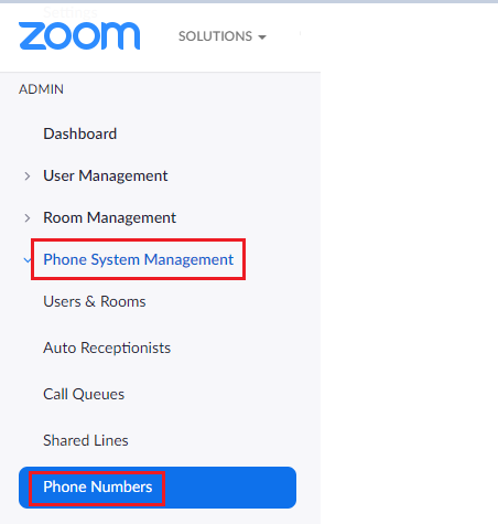
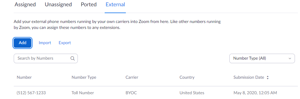
Navigate to Phone Systems Management > Phone Numbers > External.
Add External Number
External
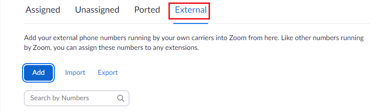
Select Add to add external phone numbers provided by your carrier into the Zoom portal. These numbers are the DID numbers provided by your carrier.
Select BYOC as the carrier.
Enter the existing customer phone numbers (from carrier) separated by commas.Add External Number
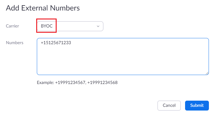
Click Submit .
Verify the external numbers have been created successfully as shown below.
External Number created successfully
Create Zoom Users
Zoom Users are created in order to login to Zoom clients on desktop or mobile. The steps for creating a user are as follows:
- Navigate to User Management > Users .
- Click Add to create new Zoom users.
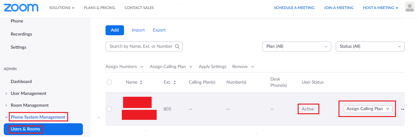
- Navigate to Phone System Management > Users & Rooms.
- Check that the User status is " Active ".
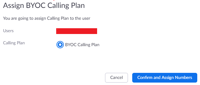
Navigate to Assign Calling Plan > Assign BYOC Calling Plan .
Click " Confirm and Assign Numbers ".
Create Zoom User
Assign BYOC calling plan
Assign the External Numbers created previously in Add External Number.
Choose from Unassigned Numbers
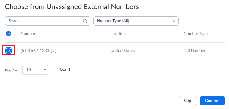
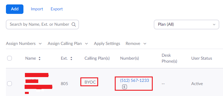
Click Confirm to finish. Once the User is assigned with a Calling Plan and Number, it should look like the following example:
Configured User
Supplementary Services Configuration on Zoom
Zoom supports multiple supplementary services. To configure different supplementary services in Zoom, refer to the following links:
1. Auto Receptionist: https://support.zoom.us/hc/en-us/articles/360001297663-Getting-started-with-Zoom-Phone-admin-#h_a625f531-94c6-4291-909e-3d68ad685b68
2. Call Flip: https://support.zoom.us/hc/en-us/articles/360034613311-Using-Call-Flip
3. Shared Line Appearance (SLA) or Call Delegation: https://support.zoom.us/hc/en-us/articles/360032881731
4. Shared Line Group/SLG: https://support.zoom.us/hc/en-us/articles/360038850792/
Supplementary Services & Features Coverage
The following checklist depicts the set of services/features covered through the configuration defined in this Interop Guide.
| Sr.No. | Supplementary Features/Services | Coverage |
|---|---|---|
| 1 | Basic Registration over UDP,TCP & TLS | N/A |
| 2 | Basic Call Setup |
|
| 3 | Basic Call Termination |
|
| 4 | Auto Receptionist (Auto Attendant) |
|
| 5 | Call Waiting |
|
| 6 | Call Hold/Resume |
|
| 7 | Call Transfer - Blind (Cold Transfer) |
|
| 8 | Call Transfer - Consult (Warm Transfer) |
|
| 9 | Call Queue |
|
| 10 | Conference |
|
| 11 | Shared Line Group (SLG) |
|
| 12 | Shared Line Appearance (SLA) or Call Delegation |
|
| 13 | Call Recording |
|
| 14 | Call Flip |
|
Legend
| Supported |
| Not Supported |
| N/A | Not Applicable |
Caveats
Note the following items in relation to this Interop:
- Potential issue has been observed on SBC 5400 for long duration calls (HOLD/UNHOLD from PSTN after 30mins) where SBC management tends to go down. The fix for this issue is available in SBC release 9.2 and beyond. We recommend to use SBC 9.2 release.
Support
For any support related queries about this guide, please contact your local Ribbon representative, or use the details below:
- Sales and Support: 1-833-742-2661
- Other Queries: 1-877-412-8867
- Website: https://ribboncommunications.com/about-us
References
For detailed information about Ribbon products & solutions, please visit:
https://ribboncommunications.com/products
For detailed information about Zoom products & solutions, please visit:
Conclusion
This Interoperability Guide describes a successful configuration covering Zoom interop involving the SBC Core. All the necessary features and serviceability aspects stand covered as per the details provided in this interoperability document.
© 2021 Ribbon Communications Operating Company, Inc. © 2021 ECI Telecom Ltd. All rights reserved.
Overview
Content Tools