| Info |
|---|
|
Visual First Call Setup is not available for SBC Cloud environments. |
The Visual First Call Setup configuration wizard is an EMA-based tool that guides you through the procedure of in configuring the SBC for processing calls in an experimental setup.Use the Visual First Call Setup tool to configure the SBC for processing low volume of calls. The most typical use case is testing a new feature of the SBC in an experimental/laboratory set up, to process calls in a laboratory (non-production) environment under light to moderate levels of traffic. Sonus recommends using other standard procedures This wizard is not intended for configuring SBCs the SBC for production deployments.
| Info |
|---|
|
The The Visual First Call Setup tool tool is a guided procedure - it maintains the a predefined order of actions that needs to be performedfrom start to finish. You are not allowed to skip one or more actions (forward or backward)cannot skip an action or go back to a previous action. |
| Info |
|---|
|
| While using this tool, try not to navigate Avoid navigating to other EMA objects or windows , as while using this tool to avoid a disrupted workflow results resulting in configuration that are an out-of synchronization. If you want to navigate to -sync configuration. Before navigating to the other EMA objects, ensure that complete and save the configuration element on which you are presently working is completely configured and saved.You may navigate to other EMA objects and configure objects that are independent of objects on the active window.You must avoid creating any object through EMA and CLI . Once you save the Visual First Call Setup configuration, you can then navigate to and configure other EMA or CLI objects, but avoid creating objects that are related to the active windowconfiguration in your saved configuration. |
| Info |
|---|
|
The Visual First Call Setup offers limited functionality in terms of wizard does not include real-time update updates of the configuration status of the objects. If you configure an object using this tool, and then delete the configuration through EMA or CLI, the tool still reflects the configuration status as "configured" , and displays the circular “Configuration Complete” green button icon adjacent to the object instead of red.rather than the expected red icon which indicates no configuration. |
| Info |
|---|
|
The "Getting Started with the SBC" panel is automatically hidden once the "First Call Setup" completes. Go to "Dashboard Settings" to re-enable the panel. Refer to Home - Dashboard. |
| Anchor |
|---|
| Feature Overview - Description |
|---|
| Feature Overview - Description |
|---|
|
To View Visual Call Setup
On the SBC main screen, navigate to Configuration > Configuration Wizards > Visual First Call Setup.
The Visual First Call Setup window is displayedopens.
| Anchor |
|---|
| Visual First Call Setup - View as Diagram |
|---|
| Visual First Call Setup - View as Diagram |
|---|
|
| Caption |
|---|
| 0 | Figure |
|---|
| 1 | Visual First Call Setup - View as Diagram |
|---|
|

|
Banner
| Anchor |
|---|
| Provision the SBC for Basic SIP Peering |
|---|
| Provision the SBC for Basic SIP Peering |
|---|
|
The banner
Provision the SBC for Basic SIP Peering (at the top of the
Visual First Call Setup window) displays information on the preliminaries of the configuration procedure.
| Anchor |
|---|
Provision the SBC for Basic SIP Peering | Provision the SBC for Basic SIP Peering | | Caption |
|---|
| 0 | Figure |
|---|
| 1 | Provision the SBC for Basic SIP Peering |
|---|
|
 Image Removed Image Removed
|
See Visual First Call Setup - View as Diagram for the banner.View
There are two options to view the entire consolidated configuration:
0View as Diagram (default)View as Table
| Caption |
|---|
1 | Figure | Diagram/ Image Removed
By default, the Visual First Call Setup window is displayed as a diagram , as illustrated in the figure Visual First Call Setup - View as Diagram.
To see view the consolidated configuration in tabular form, select View as Table:
| Caption |
|---|
| 0 | Figure |
|---|
| 1 | Visual First Call Setup - View as Table |
|---|
|

|
| Info |
|---|
|
The gear icon  is not displayed when the configuration is viewed as a table. The tabular presentation is suitable for viewing the configuration, but to configure the SBC using the Visual First Call Setup tool, switch to View as Diagram. is not displayed when the configuration is viewed as a table. The tabular presentation is suitable for viewing the configuration, but to configure the SBC using the Visual First Call Setup tool, switch to View as Diagram. |
Special Case - Fresh Installation/Upgrade
If the SBC is not configured using the Visual First Call Setup tool, as in case of a freshly installed/upgraded SBC:
When viewed as diagram, instead of a green circle, a red circle is displayed beside each configuration element. For more information, see Provision the SBC for Basic SIP Peering.
| Caption |
|---|
| 0 | Figure |
|---|
| 1 | (Not Configured) Visual First Call Setup - View as Diagram |
|---|
|

|
Except With the exception of Customer Network > PBX and Carrier Network > Carrier, all other configuration elements remain inactive; this is to ensure that the sequence of the configuration is maintained.
When viewed as table, the table is displayed only with fields but no values.
| Caption |
|---|
| 0 | Figure |
|---|
| 1 | (Not Configured) Visual First Call Setup - View as Table |
|---|
|

|
Configuration Elements
Follow the Configuration Elements Hierarchy to configure the elements displayed in the Visual First Call Setup window.
| Anchor |
|---|
| Configuration Elements Hierarchy |
|---|
| Configuration Elements Hierarchy |
|---|
|
Customer NetworkCarrier Network<CE Name>
Internal/Core/Trusted SideIP Interface GroupStatic RouteZoneSIP Trunk GroupSIP Signaling PortIP Peer
External/Carrier/Untrusted SideIP Interface GroupStatic RouteZoneSIP Trunk GroupSIP Signaling PortIP Peer
Routing
To Configure Customer NetworkConfiguring Elements
| Div |
|---|
|
Internal/Core/Trusted Side | | To configure this element... | Click the gear icon adjacent to |
|---|
|
Customer Network > PBX.| Caption |
|---|
|
 Image Removed Image Removed
|
| : | This dialog box will open. | Next steps: | Sample screen |
|---|
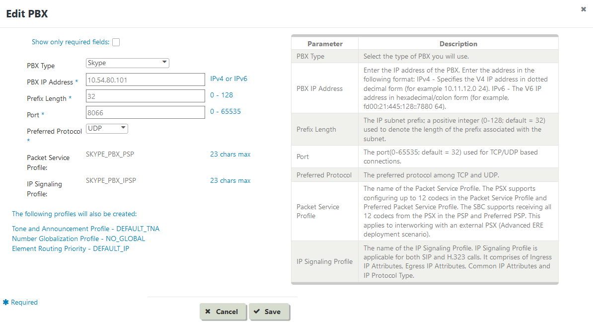
Customer Network | Customer Network > PBX | Edit PBX |
|
The Edit PBX dialog box is displayed.
| Anchor |
|---|
Edit PBX | Edit PBX | | Caption |
|---|
|
 Image Removed
 | Enter values in the fields and |
|
click then click Save. To restore the fields to defaults, |
|
click Cancel.
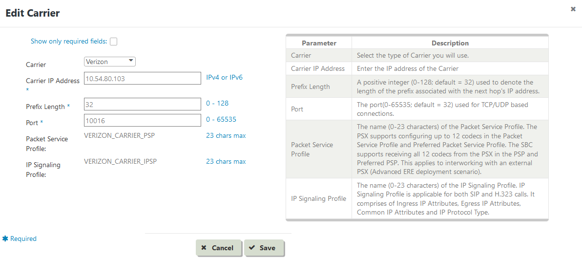
Click the gear icon adjacent to Carrier Network > CarrierCarrier Image Removed
| Caption |
|---|
| 0 | Figure |
|---|
1 |  Image Added Image Added
|
|
|
The Edit Carrier dialog box is displayed.Carrier Network | Carrier Network |
|
 Image Removed Image Removed
|
Enter values in the fields and |
|
click then click Save. To restore the fields to defaults, |
|
click
To Configure | Caption |
|---|
|  Image Added Image Added
|
| | CE Internal/Core/Trusted Side |
|
To Configure Click the gear icon adjacent to .caption| Caption |
|---|
| 0 | Figure |
|---|
1 | | 0 | Figure |
|---|
| 1 | IP Interface Group |
|---|
|
 Image Removed Image Removed
|
The Edit IP Interface Group dialog box is displayed. Image Removed Image Removed
|
Enter values in the fields and |
|
click then click Save. To restore the fields to defaults, |
|
click To Configure IP InterfaceClick the gear icon adjacent to IP Interface.| Caption |
|---|
| 0 | Figure |
|---|
1 | | Caption |
|---|
| 0 | Figure |
|---|
| 1 | Edit IP Interface Group |
|---|
|
|
|
 Image Removed Image Removed
|
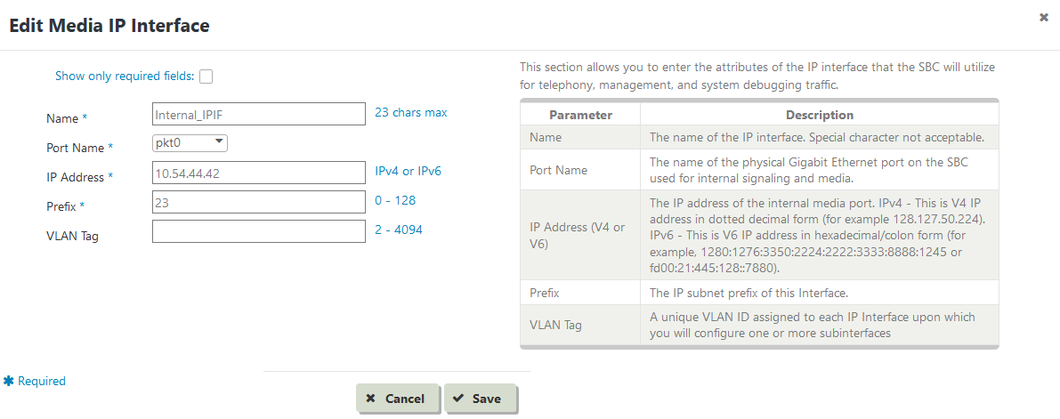
The Edit Media IP Interface dialog box is displayed. Image Added Image Added
|
| | CE Internal/Core/Trusted Side - IP Interface | IP Interface |
|
 Image Removed Image Removed
|
Enter values in the fields and |
|
click then click Save. To restore the fields to defaults, |
|
click Cancel.Click the gear icon adjacent to Static RouteEdit click Cancel. | | Caption |
|---|
| 0 | Figure |
|---|
| 1 | Edit Media IP Interface |
|---|
|  Image Added Image Added
|
| | Static Route |
|
 Image Removed Image Removed
|
The dialog box is displayed.| 0 | Figure |
|---|
1 | | Caption |
|---|
Route Image Removed
| Route | Enter values in the fields and |
|
click then click Save. To restore the fields to defaults, |
|
click Cancel.Click the gear icon adjacent to ZoneZone Image RemovedEdit
  Image Added Image Added
|
|
|
The dialog box is displayed.| Caption |
|---|
| 0 | Figure |
|---|
1 Image Removed Image Removed
|
Enter values in the fields and |
|
click then click Save. To restore the fields to defaults, |
|
click Cancel.Click the gear icon adjacent to SIP Trunk GroupEdit click Cancel. | | Caption |
|---|
|  Image Added Image Added
|
| | SIP Trunk Group |
|
 Image Removed Image Removed
|
The dialog box is displayed.| 0 | Figure |
|---|
1 | | Caption |
|---|
 Image Removed
 | Enter values in the fields and |
|
click then click Save. To restore the fields to defaults, |
|
click Cancel.Click the gear icon adjacent to SIP Signaling Portclick Cancel. | | Caption |
|---|
| 0 | Figure |
|---|
| 1 | Edit SIP Trunk Group |
|---|
|  Image Added Image Added
|
| | SIP Signaling Port |
|
 Image RemovedThe dialog box is displayed
 | Enter values in the fields and then click Save. To restore the fields to defaults, click Cancel. | | Caption |
|---|
| 0 | Figure |
|---|
| 1 | Edit SIP Signaling Port |
|---|
|
|
|
 Image Removed
 Image Added Image Added
|
| | IP Peer | IP Peer | Edit IP Peer | Enter values in the fields and |
|
click then click Save. To restore the fields to defaults, |
|
click To Configure |  Image Added Image Added
|
| | External/Carrier/Untrusted Side | | To configure this element... | Click the gear icon adjacent to |
|---|
|
IP Peer| : | This dialog box will open. | Next steps: | Sample screen |
|---|
| IP Interface Group | IP Interface Group | Edit IP Interface Group | Enter values in the fields and then click Save. To restore the fields to defaults, click Cancel. | |
|
IP Peer |  Image Removed Image Removed
|
The Edit IP Peer dialog box is displayed |  Image Added Image Added
|
| | Media IP Interface | Media IP Interface | Edit Media IP Interface | Enter values in the fields and then click Save. To restore the fields to defaults, click Cancel. | |
|
IP Peer Image Removed
 |  Image Added Image Added
|
| | Static Route | Static Route | Edit Static Route | Enter values in the fields and |
|
click then click Save. To restore the fields to defaults, |
|
click Click the gear icon adjacent to IP Interface Group | | Caption |
|---|
| 0 | Figure |
|---|
| 1 | Edit Static Route |
|---|
|  Image Added Image Added
|
| | Zone | Zone | Edit Zone | Enter values in the fields and then click Save. To restore the fields to defaults, click Cancel. | |
|
IP Interface |  Image Added Image Added
|
| | SIP Trunk Group |
|
 Image RemovedThe IP Interface Group dialog box is displayed
| SIP Trunk Group | Enter values in the fields and then click Save. To restore the fields to defaults, click Cancel. | |
|
IP Interface Group Image Removed
 |  Image Added Image Added
|
| | SIP Signaling Port | SIP Signaling Port | Edit SIP Signaling Port | Enter values in the fields and |
|
click then click Save. To restore the fields to defaults, |
|
click Click the gear icon adjacent to Media IP Interface.| Caption |
|---|
| 0 | Figure |
|---|
| 1 | Edit SIP Signaling Port |
|---|
|  Image Added Image Added
|
|
|
Media Interface Image RemovedThe Media IP Interface dialog box is displayed
| IP Peer | Enter values in the fields and then click Save. To restore the fields to defaults, click Cancel. | |
|
Media IP Interface Image Removed
 |  Image Added Image Added
|
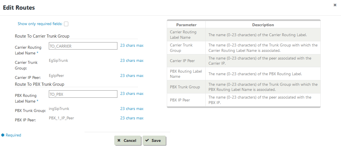
| | Routing | Routing | Edit Routes | Enter values in the fields and |
|
click then click Save. To restore the fields to defaults, |
|
click click Cancel. | | Caption |
|---|
|  Image Added Image Added
|
|
|
| Info |
|---|
| title | Note - Error Messages |
|---|
|
While configuring various elements of the Visual First Call Setup tool, you may encounter error messages of two types: - Error messages that results from unacceptable values entered against the fields. These error messages are generated on the front-end of the EMA web application, and the Javascript code running on your browser displays such messages promptly.
- Error messages you receive from the back-end of the EMA web application. A small web server runs on the SBC, which serves the EMA application over http/https protocol. Sometimes, the code running on the web server finds values that you enter against the fields as unacceptable due to constraints placed by the back-end logic, even if the values are within the bounds imposed by
|
Sonus- . For example, if you set the field
Port Name as pkt0 (displayed on the Edit Media IP Interface window) for both Internal (PBX) as well as External (Carrier) side of the setup, an error message is generated from the back-end and displayed on your browser
|
.Click the gear icon adjacent to Static Route.
| Caption |
|---|
|
 Image Removed Image Removed
|
The Edit Static Route dialog box is displayed.
| Caption |
|---|
| 0 | Figure |
|---|
| 1 | Edit Static Route |
|---|
|
 Image Removed Image Removed
|
- Enter values in the fields and click Save. To restore the fields to defaults, click Cancel.
Click the gear icon adjacent to Zone.
| Caption |
|---|
|
 Image Removed Image Removed
|
The Edit Zone dialog box is displayed.
| Caption |
|---|
|
 Image Removed Image Removed
|
Enter values in the fields and click Save To restore the fields to defaults, click Cancel.Click the gear icon adjacent to SIP Trunk Group.
| Caption |
|---|
|
 Image Removed Image Removed
|
The Edit SIP Trunk Group dialog box is displayed.
| Caption |
|---|
| 0 | Figure |
|---|
| 1 | Edit SIP Trunk Group |
|---|
|
 Image Removed Image Removed
|
- Enter values in the fields and click Save. To restore the fields to defaults, click Cancel.
Click the gear icon adjacent to SIP Signaling Port.
| Caption |
|---|
| 0 | Figure |
|---|
| 1 | SIP Signaling Port |
|---|
|
 Image Removed Image Removed
|
The Edit SIP Signaling Port dialog box is displayed.
| Caption |
|---|
| 0 | Figure |
|---|
| 1 | Edit SIP Signaling Port |
|---|
|
 Image Removed Image Removed
|
- Enter values in the fields and click Save. To restore the fields to defaults, click Cancel.
Click the gear icon adjacent to IP Peer.
| Caption |
|---|
|
 Image Removed Image Removed
|
The Edit IP Peer dialog box is displayed.
| Caption |
|---|
|
 Image Removed Image Removed
|
- Enter values in the fields and click Save. To restore the fields to defaults, click Cancel.
Click the gear icon adjacent to Routing.
| Caption |
|---|
|
 Image Removed Image Removed
|
The Edit Routing dialog box is displayed.
| Caption |
|---|
|
 Image Removed Image Removed
|
- Enter values in the fields and click Save. To restore the fields to defaults, click Cancel.


