The Tenor can be used to provide FXS analog capability to the
(SBC), allowing for FAX connectivity. In this article, we describe the steps necessary to deploy a Tenor as an analog device in aSBC
- Lync SBA topology. The overall configuration comprises three components: the
Lync Server, the
Tenor, and theSBC:
| Note |
|---|
In this article, G.711 voice codec is used and CNG Tone Detection is disabled:
When CNG detection is disabled, theSBC lets the Calling fax machine on either side, ISDN or SIP, to send CNG. However, theSBC is actively listening for and detecting the Fax Answer message that the Answering fax machine sends because Fax pass-thru is enabled. |
The following diagrams depict the signaling and media flow of the Analog End Point of LYNC in this deployment.
Outbound Fax call flow using Lync call control (signaling and media) |
|---|

|
Inbound Fax call flow using Lync call control (signaling and media) |
|---|

|
Related Information
In this deployment, following LYNC topology entities, PBX, and numbering plans are used:
| | Background Color |
|---|
| | IP Address |
| | Background Color |
|---|
| | Description |
|
|---|
| Background Color |
|---|
| | uxdemo.net |
| | Background Color |
|---|
| | 134.56.105.30 |
| | Background Color |
|---|
| | LYNC SBA Domain |
|
| Background Color |
|---|
| | rdc.uxdemo.net |
| | Background Color |
|---|
| | 134.56.105.30 |
| | Background Color |
|---|
| | DNS/AD/Ent. Root CA |
|
| Background Color |
|---|
| | sba247.uxdemo.net |
| | Background Color |
|---|
| | 134.56.105.247 |
| | Background Color |
|---|
| | FQDN of Lync SBA Pool |
|
| Background Color |
|---|
| | ux246.uxdemo.net |
| | Background Color |
|---|
| | 134.56.105.246 |
| | Background Color |
|---|
| | FQDN of the SBC GW |
|
| | Background Color |
|---|
| | 134.56.105.41 |
| | Background Color |
|---|
| | Analog Device |
|
| Background Color |
|---|
| | Nortel Meridian |
| | |
| Background Color |
|---|
| | LYNC SBA Users |
| |
|---|
| Background Color |
|---|
| | sip:SBAuser1@uxdemo.net |
| | Background Color |
|---|
| | tel:+15102461001 |
|
| Background Color |
|---|
| | sip:SBAuser2@uxdemo.net |
| | Background Color |
|---|
| | tel:+15102461002 |
|
| Background Color |
|---|
| | LYNC SBA ANALOG Users |
| |
|---|
| Background Color |
|---|
| | sip:ae11467d-d09d-4e78-ad2a-e4615b79ac57@Ribbon1000/2000DEMO.Ribbon (ANALOGph1) |
| | Background Color |
|---|
| | tel:+15102462001 |
|
| Background Color |
|---|
| | sip:80274280-9a22-43d9-b194-2640904c3e54@Ribbon SBC 1000/2000DEMO.Ribbon (ANALOGph2) |
| | Background Color |
|---|
| | tel:+15102462002 |
|
| Background Color |
|---|
| | sip:3f1e38d7-c8a3-425a-818c-bae3f2c28d62@Ribbon SBC 1000/2000DEMO.Ribbon (Fax1) |
| | Background Color |
|---|
| | tel:+15102462003 |
|
| Background Color |
|---|
| | Meridian Endpoints |
| | Background Color |
|---|
| | Extensions |
|
|---|
| | Background Color |
|---|
| | ext: 6228 |
|
| | Background Color |
|---|
| | ext: 6222 |
|
Before You Begin
The SBC SBA must already be configured. If not, configure and deploy the Lync SBA following the instructions in Preparing for SBA Deployment - First Steps.
Lync Configuration
Creating analog End Point using the New-CsAnalogDevice Command
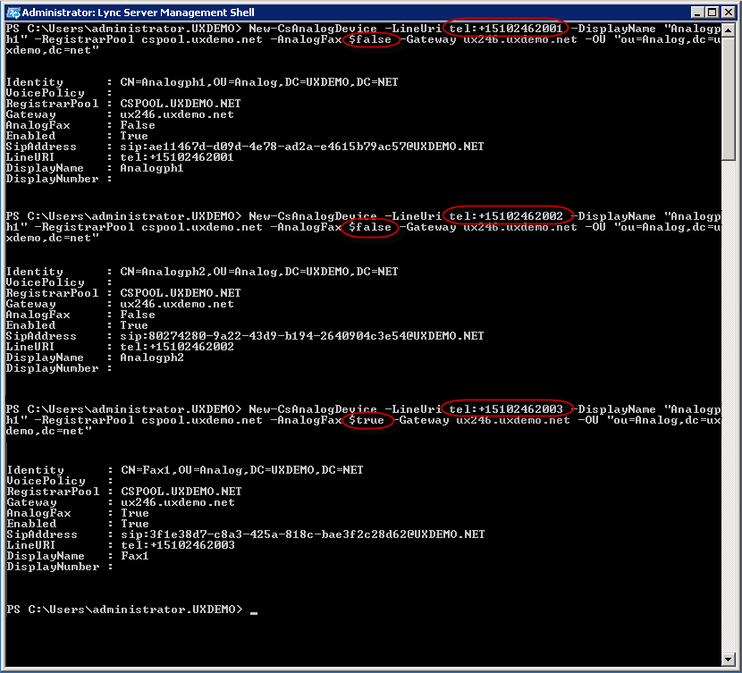
Analog Endpoints must be created from the Lync Management Shell using the New-CsAnalogDevice cmdlet.
- On the Lync Server, go to Start > Microsoft Lync Server 2010 > Lync Server Management Shell.
Enter the command as shown below.
For Aanalog Phone Endpoints:
| Code Block |
|---|
New-CsAnalogDevice \-LineUri tel:+15102462001 \-DisplayName "Analogph1" \-RegistrarPool cspool.uxdemo.net \-AnalogFax $false \-Gateway ux246.uxdemo.net \-OU "ou=Analog,dc=uxdemo,dc=net"
|
For Analog FAX Endpoints:
| Code Block |
|---|
New-CsAnalogDevice \-LineUri tel:+15102462003 \-DisplayName "Fax1" \-RegistrarPool cspool.uxdemo.net \-AnalogFax $true \-Gateway ux246.uxdemo.net \-OU "ou=Analog,dc=uxdemo,dc=net"
|
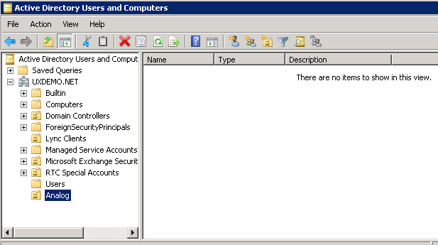
 Before running the commands above, make sure that the relevant Organizational Unit(OU) (in this example it is named Analog) exists in Active Directory. On a machine that can access the Active Directory Users and Computers snap-in, launch the Active Directory Users and Computers snap-in and verify that OU is present as shown in below screenshot:
| Panel |
|---|
|
| Caption |
|---|
| 0 | Figure |
|---|
| 1 | Verify OU Is Present |
|---|
| 
|
|
- Launch the Lync Management Shell and run the relevant commands to create both Analog Phone and Analog Fax Endpoints as shown in below screenshot:
| Panel |
|---|
|
| Caption |
|---|
| 0 | Figure |
|---|
| 1 | Launch Lync Management Shell |
|---|
| 
|
|
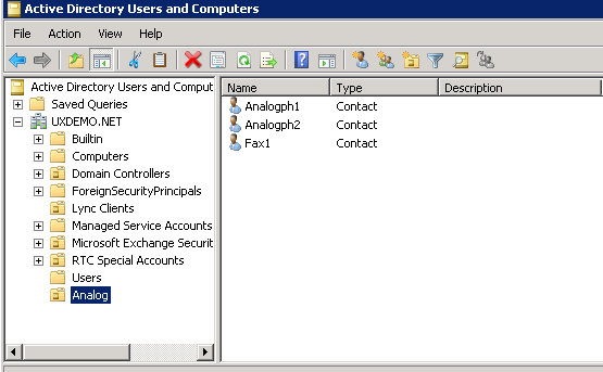
- Verify in Active Directory Users and Computers snap-in that relevant users are created successfully in Analog Organizational Unit as shown below:
| Panel |
|---|
|
| Caption |
|---|
| 
|
|
Explanation of New-CsAnalogDevice
The New-CsAnalogDevice cmdlet instructs Lync to route calls from the analog device to the gateway specified in the -Gateway switch of the cmdlet; thus, ensuring that Fax calls will safely be transmitted over PSTN.
Tenor configuration
Requirements for Tenor
These instructions assume that:
- The Tenor gateway is running P108-09-10 or newer software release.
- The Tenor Configuration Manager is CM108-19-00 or newer.
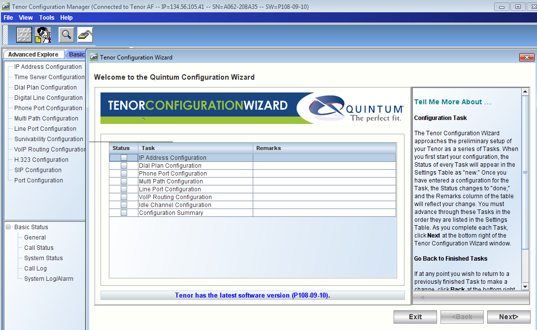
Run the Tenor Wizard
- Launch the Quintum Configuration Manager and connect to your Tenor Device
- Upon connecting to the device, Configuration Wizard will run automatically
- Follow the Wizard Steps and enter the relevant IP addresses, Analog Endpoint numbers..etc. as shown below
| Panel |
|---|
|
| Caption |
|---|
| 
|
|
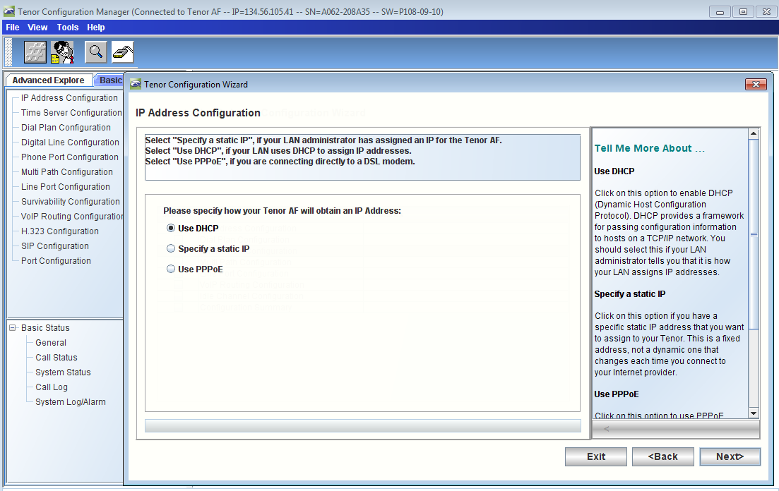
- For this exercise we are using DHCP for the Tenor IP address configuration
| Panel |
|---|
|
| Caption |
|---|
| 0 | Figure |
|---|
| 1 | IP Address Configuration - DHCP |
|---|
| 
|
|
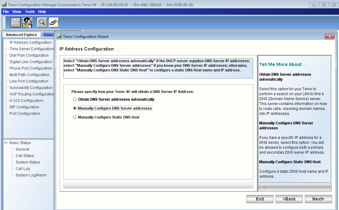
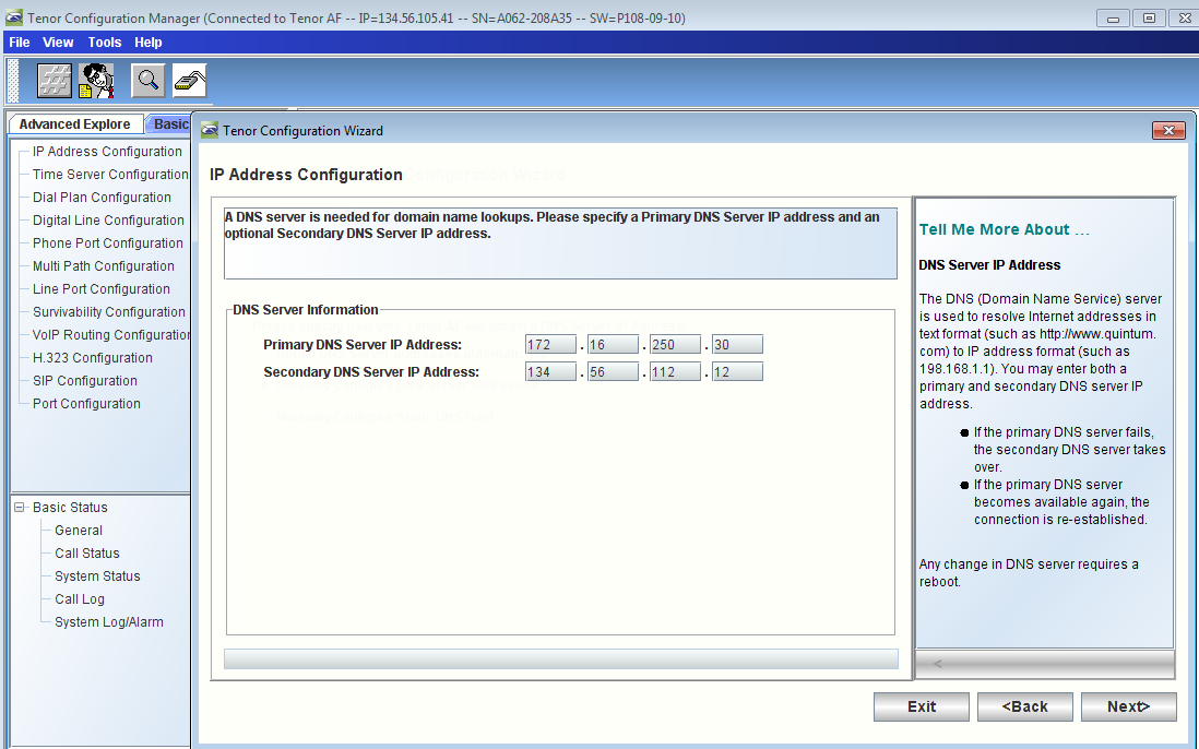
- Enter the DNS IP address which is used in LYNC SBA Deployment Topology
| Panel |
|---|
|
| Caption |
|---|
| 0 | Figure |
|---|
| 1 | IP Address Configuration - DNS |
|---|
| 
|
|
| Panel |
|---|
|
| Caption |
|---|
| 0 | Figure |
|---|
| 1 | Enter DNS IP Address |
|---|
| 
|
|
- Verify that IP Address Configuration is completed as shown below
| Panel |
|---|
|
| Caption |
|---|
| 0 | Figure |
|---|
| 1 | Verify IP Address Configuration |
|---|
| 
|
|
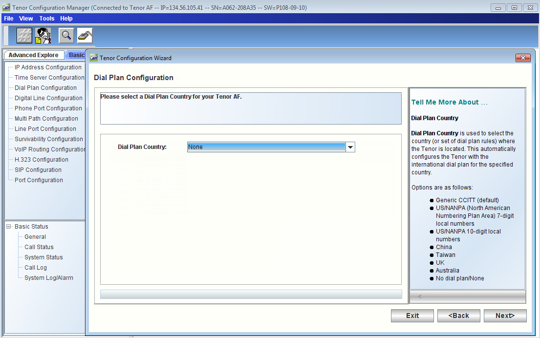
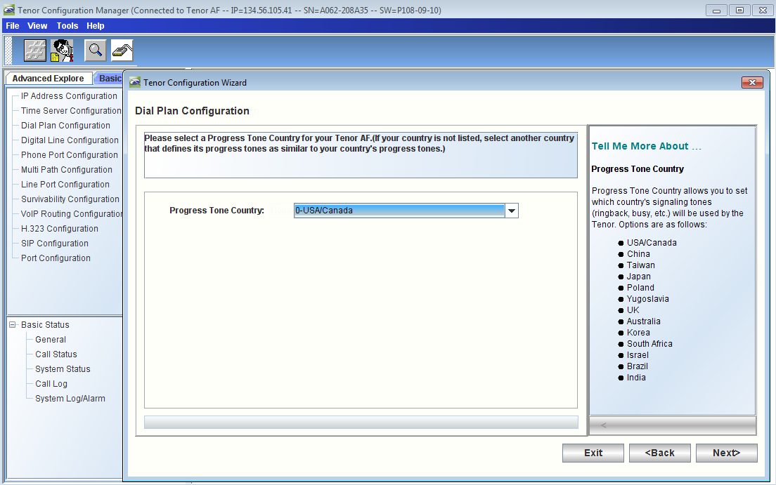
- Continue the wizard steps for Dial Plan Configuration
| Panel |
|---|
|
| Caption |
|---|
| 0 | Figure |
|---|
| 1 | Dial Plan Country |
|---|
| 
|
|
| Panel |
|---|
|
| Caption |
|---|
| 0 | Figure |
|---|
| 1 | Progress Tone Country |
|---|
| 
|
|
- Verify that Dial Plan Configuration is completed as shown below
| Panel |
|---|
|
| Caption |
|---|
| 0 | Figure |
|---|
| 1 | Verify Dial Plan Configuration |
|---|
| 
|
|
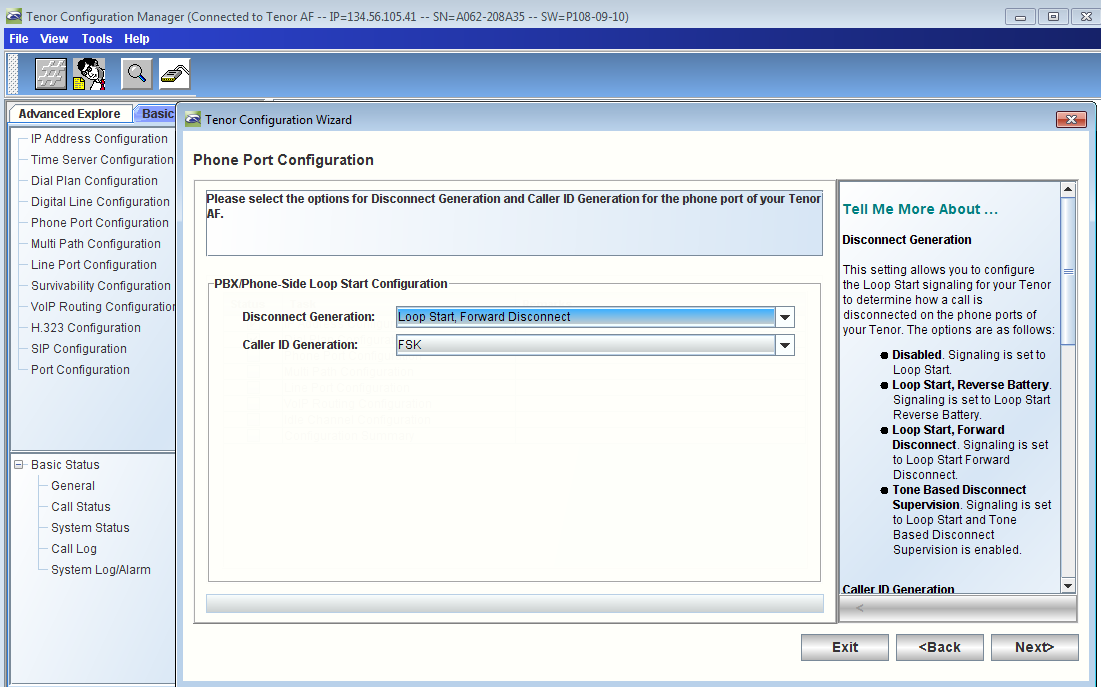
- Continue the wizard steps for Phone Port Configuration
| Panel |
|---|
|
| Caption |
|---|
| 0 | Figure |
|---|
| 1 | Phone Port Configuration |
|---|
| 
|
|
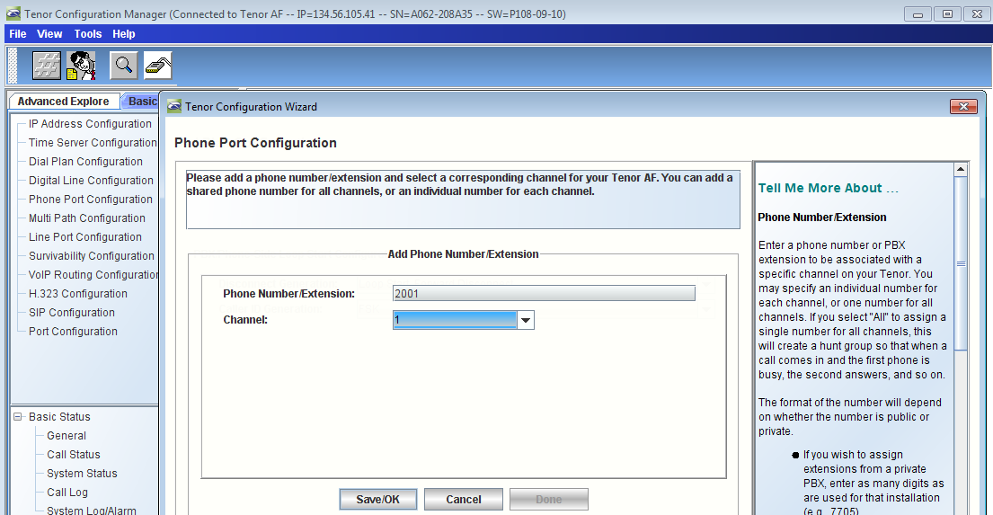
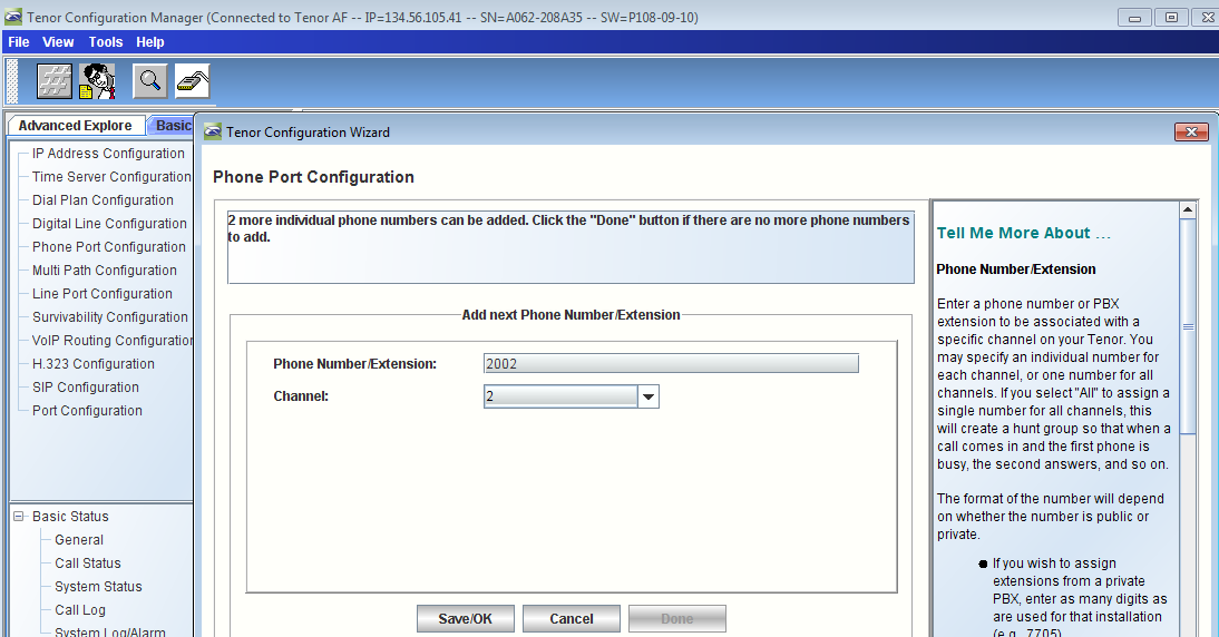
- Enter the relevant Phone Number/Extension (in this example we are using 2001 and 2002 users for the Analog phone endpoints)
| Panel |
|---|
|
| Caption |
|---|
| 0 | Figure |
|---|
| 1 | Enter Phone Number/Extension - 2001 |
|---|
| 
|
|
| Panel |
|---|
|
| Caption |
|---|
| 0 | Figure |
|---|
| 1 | Enter Phone Number/Extension - 2002 |
|---|
| 
|
|
- Hit on Click "Save/OK" and then the "Done" buttons
| Panel |
|---|
|
| Caption |
|---|
| 0 | Figure |
|---|
| 1 | Add Phone Number/Extension |
|---|
| 
|
|
| Panel |
|---|
|
| Caption |
|---|
| 0 | Figure |
|---|
| 1 | Configured Phone Number/Extension |
|---|
| 
|
|
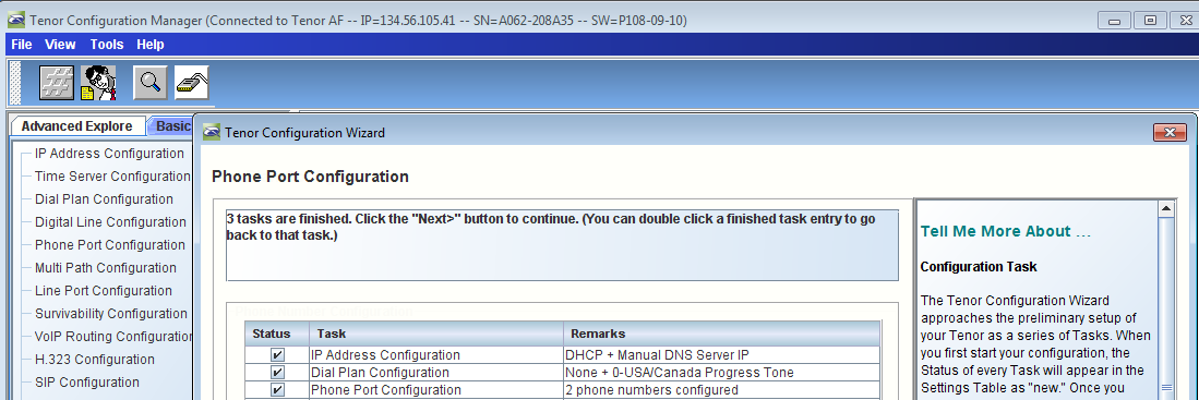
- Verify that Phone Port Configuration is completed as shown below
| Panel |
|---|
|
| Caption |
|---|
| 0 | Figure |
|---|
| 1 | Verify Phone Port Configuration |
|---|
| 
|
|
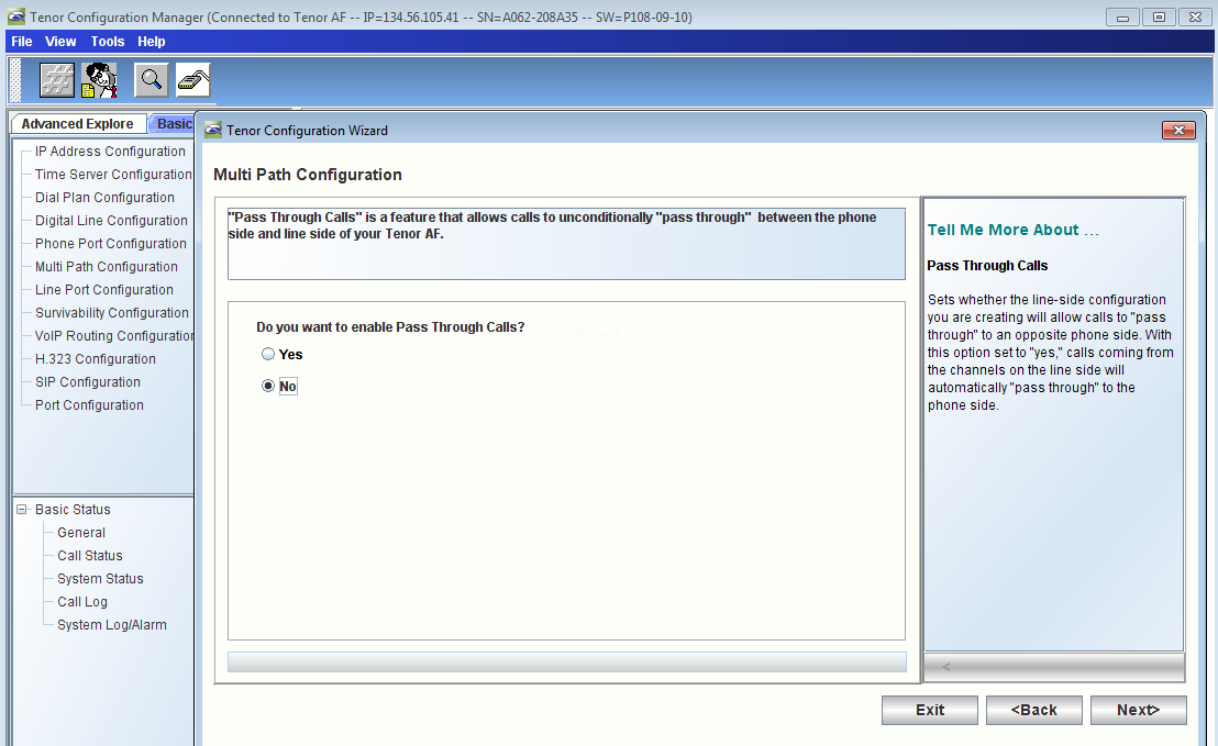
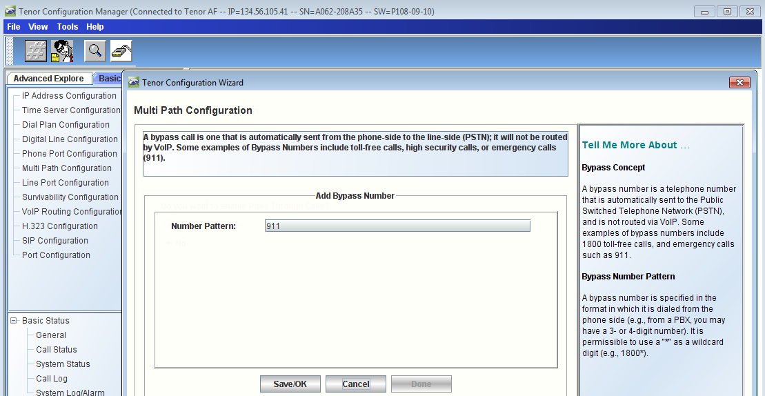
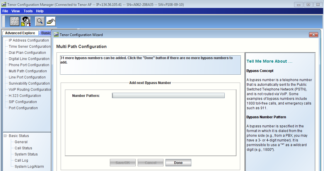
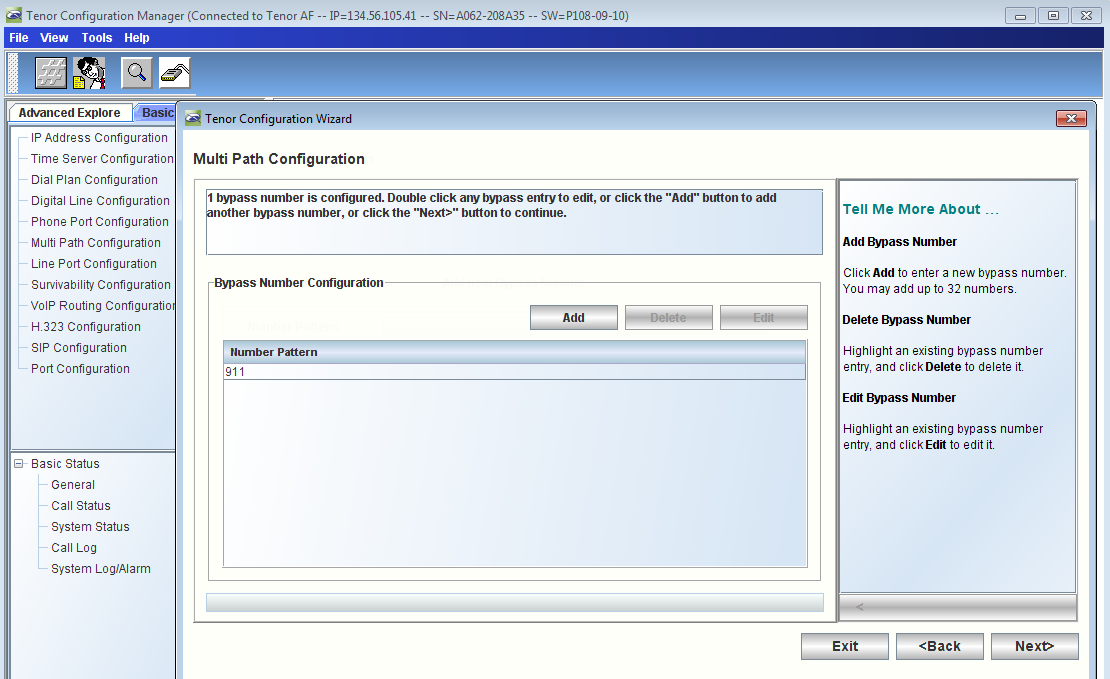
- Continue the wizard steps for Multi Path Configuration
| Panel |
|---|
|
| Caption |
|---|
| 0 | Figure |
|---|
| 1 | Enable Pass Through Calls |
|---|
| 
|
|
| Panel |
|---|
|
| Caption |
|---|
| 0 | Figure |
|---|
| 1 | Add Bypass Number |
|---|
| 
|
|
| Panel |
|---|
|
| Caption |
|---|
| 0 | Figure |
|---|
| 1 | Add Next Bypass Number |
|---|
| 
|
|
| Panel |
|---|
|
| Caption |
|---|
| 0 | Figure |
|---|
| 1 | Configure Bypass Number |
|---|
| 
|
|
- Verify that Multi Path Configuration is completed as shown below
| Panel |
|---|
|
| Caption |
|---|
| 0 | Figure |
|---|
| 1 | Verify Multi Path Configuration |
|---|
| 
|
|
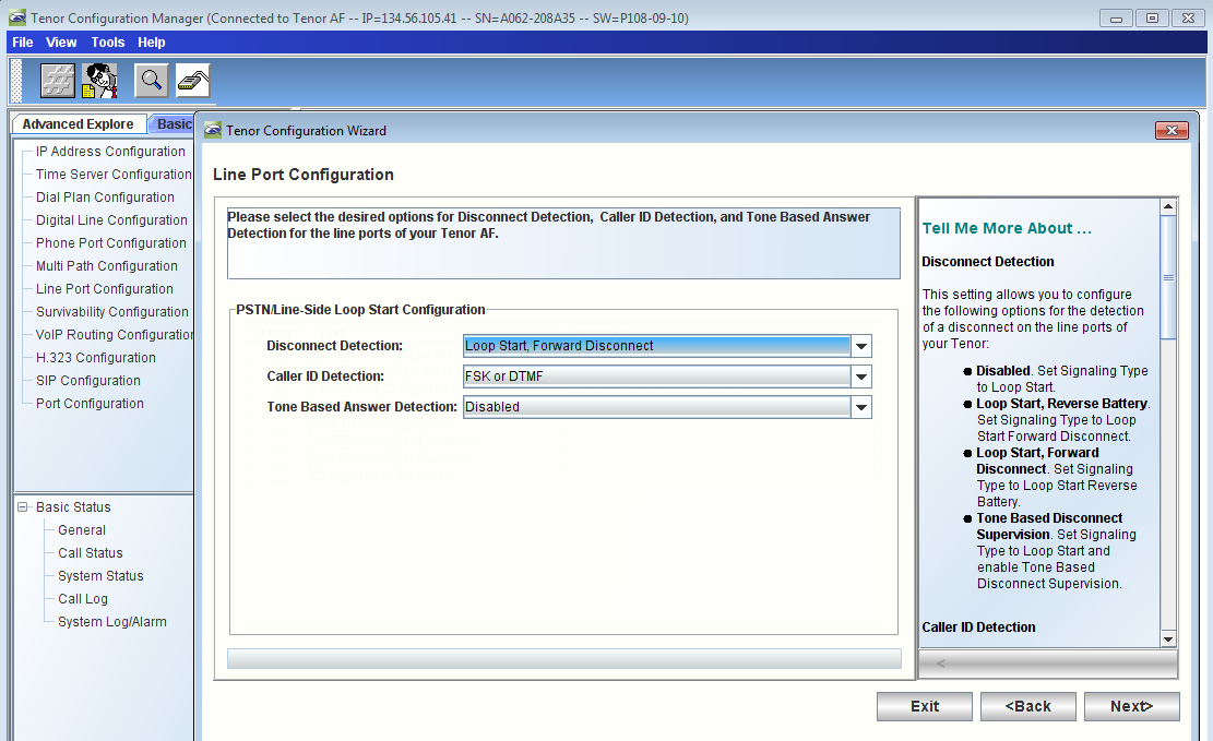
- Continue the wizard steps for Line Port Configuration
| Panel |
|---|
|
| Caption |
|---|
| 0 | Figure |
|---|
| 1 | Line Port Configuration |
|---|
| 
|
|
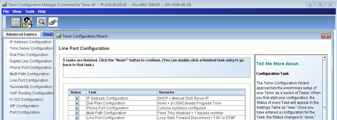
- Verify that Line Port Configuration is completed as shown below
| Panel |
|---|
|
| Caption |
|---|
| 0 | Figure |
|---|
| 1 | Verify Line Port Configuration |
|---|
| 
|
|
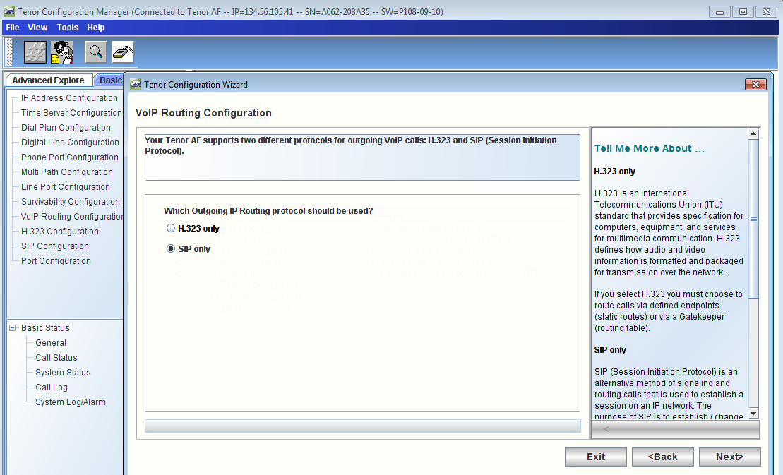
- Continue the wizard steps for VoIP Routing Configuration
| Panel |
|---|
|
| Caption |
|---|
| 0 | Figure |
|---|
| 1 | VoIP Routing Configuration |
|---|
| 
|
|
- Enter theSBC 2000 Gateway IP address in the Primary SIP Server IP/Domain Name field and the relevant Port (5060 in this case)
| Panel |
|---|
|
| Caption |
|---|
| 
|
|
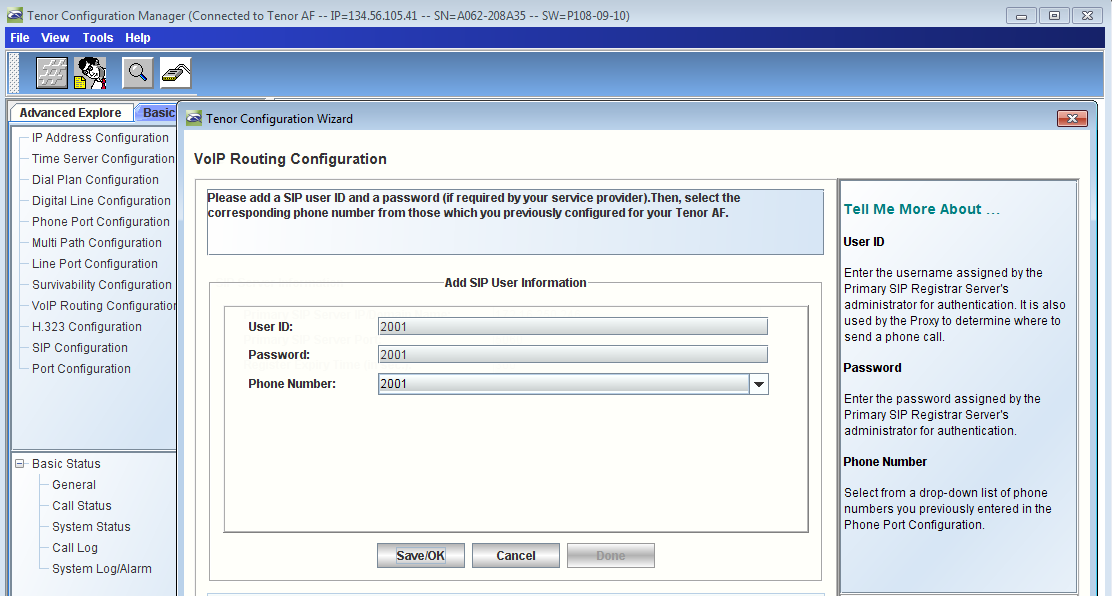
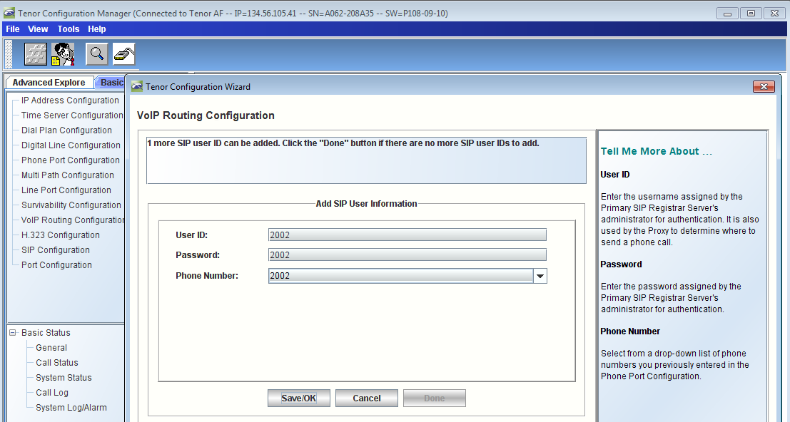
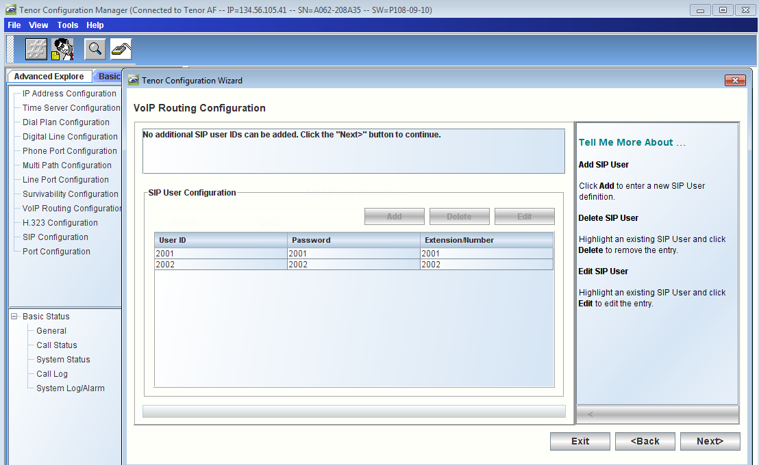
- Enter the SIP user information for the related 2001 and 2002 users
| Panel |
|---|
|
| Caption |
|---|
| 0 | Figure |
|---|
| 1 | Enter SIP User Information - 2001 |
|---|
| 
|
|
| Panel |
|---|
|
| Caption |
|---|
| 0 | Figure |
|---|
| 1 | Enter SIP User Information - 2002 |
|---|
| 
|
|
| Panel |
|---|
|
| Caption |
|---|
| 0 | Figure |
|---|
| 1 | SIP User Configuration |
|---|
| 
|
|
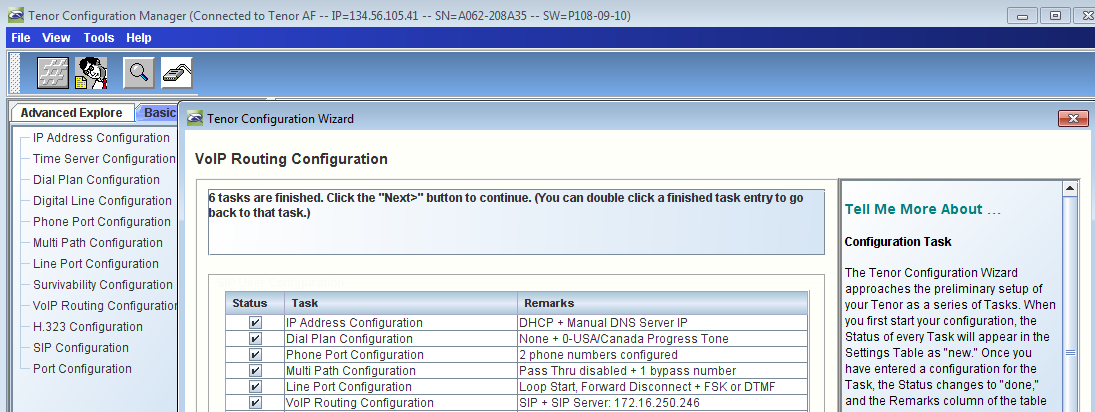
- Verify that VoIP Routing Configuration is completed as shown below
| Panel |
|---|
|
| Caption |
|---|
| 0 | Figure |
|---|
| 1 | Verify VoIP Routing Configuration |
|---|
| 
|
|
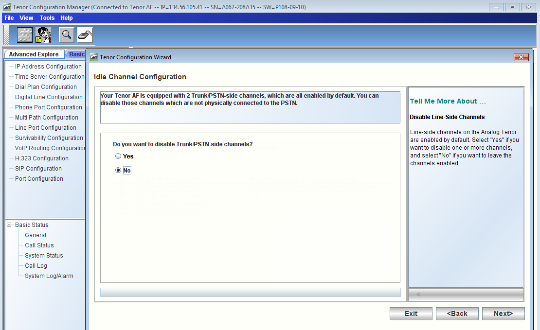
- Continue the wizard steps for Idle Channel Configuration
| Panel |
|---|
|
| Caption |
|---|
| 0 | Figure |
|---|
| 1 | Idle Channel Configuration |
|---|
| 
|
|
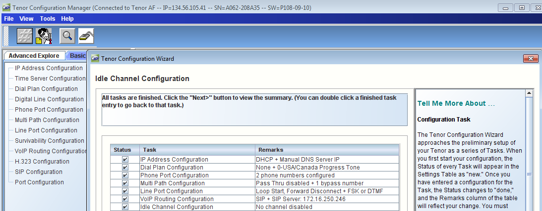
- Verify that Idle Channel Configuration is completed as shown below
| Panel |
|---|
|
| Caption |
|---|
| 0 | Figure |
|---|
| 1 | Verify Idle Channel Configuration |
|---|
| 
|
|
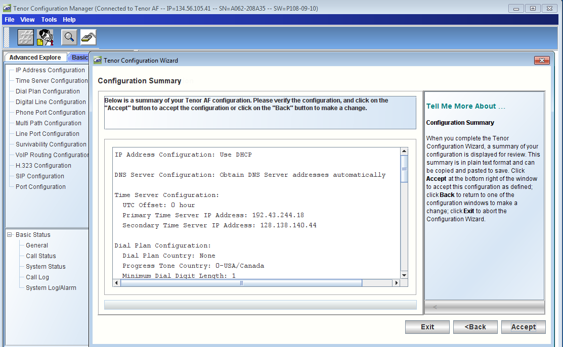
- Hit on Click the Accept button on Configuration Summary to complete the wizard run
| Panel |
|---|
|
| Caption |
|---|
| 0 | Figure |
|---|
| 1 | Complete Wizard Run |
|---|
| 
|
|
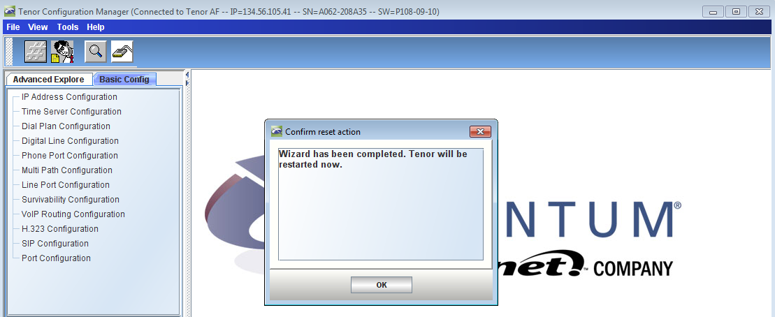
- Hit Click OK to restart the Tenor device as shown below
| Panel |
|---|
|
| Caption |
|---|
| 0 | Figure |
|---|
| 1 | Restart Tenor Device |
|---|
| 
|
|
Additional Post-wizard Settings and Configuration Verrification
Verifying the SIP Signaling Group Options
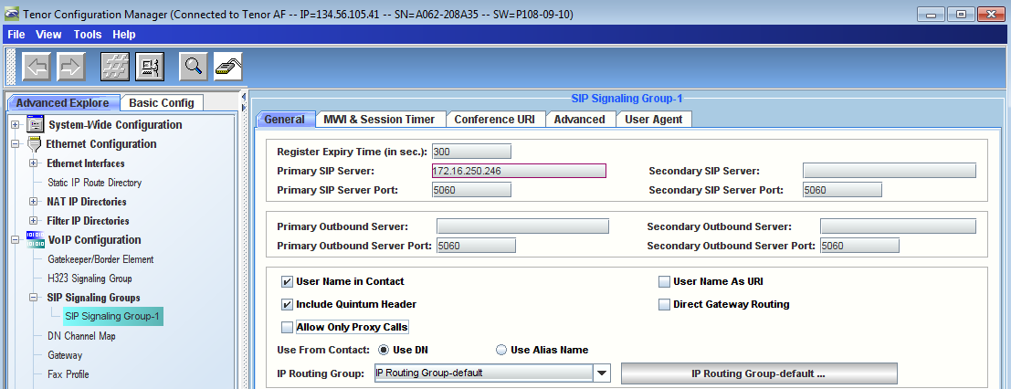
- Reconnect to Tenor Device using the Configuration Manager and Verify that SIP Signaling Group is configured In General Tab as shown below
| Panel |
|---|
|
| Caption |
|---|
| 0 | Figure |
|---|
| 1 | Reconnect to Tenor Device |
|---|
| 
|
|
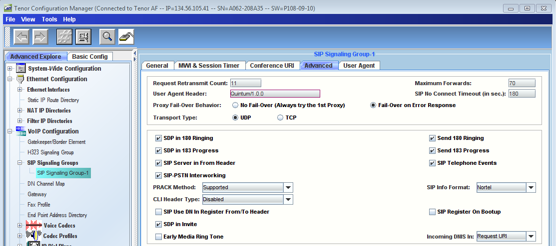
- Verify that SIP Signaling Group is configured in Advanced Tab as shown below
| Warning |
|---|
The Transport Type must be set to UDP. |
| Panel |
|---|
|
| Caption |
|---|
| 0 | Figure |
|---|
| 1 | Verify SIP Signaling Group Is Configured |
|---|
| 
|
|
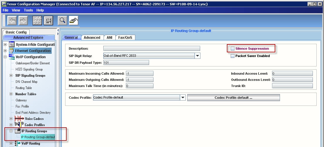
Verify that the Silence Suppression parameter in the IP Routing Group is disabled
| Panel |
|---|
|
| Caption |
|---|
| 0 | Figure |
|---|
| 1 | Disable Silence Suppression |
|---|
| 
|
|
Verify the Tx/Rx Gain Values in the CAS Signaling Groups
Verify the following settings in Tenor:
CAS Signaling Group | Rx Gain | Tx Gain |
|---|
CAS Signaling Group - Phone: | -6 | 0 |
CAS Signaling Group - Line: | 6 | 0 |
- Verify Tx/Rx gain values in the CAS signaling groups - Phone
| Panel |
|---|
|
| Caption |
|---|
| 0 | Figure |
|---|
| 1 | CAS Signaling Group - Phone |
|---|
| 
|
|
- Verify Tx/Rx gain values in the CAS signaling groups - Line
| Panel |
|---|
|
| Caption |
|---|
| 0 | Figure |
|---|
| 1 | CAS Signaling Group - Line |
|---|
| 
|
|
Creating a Route For Calls From Tenor to Lync
- In Configuration Manager, right click on Number Tables in left pane and select New as shown below
| Panel |
|---|
|
| Caption |
|---|
| 0 | Figure |
|---|
| 1 | Create New Number Table |
|---|
| 
|
|
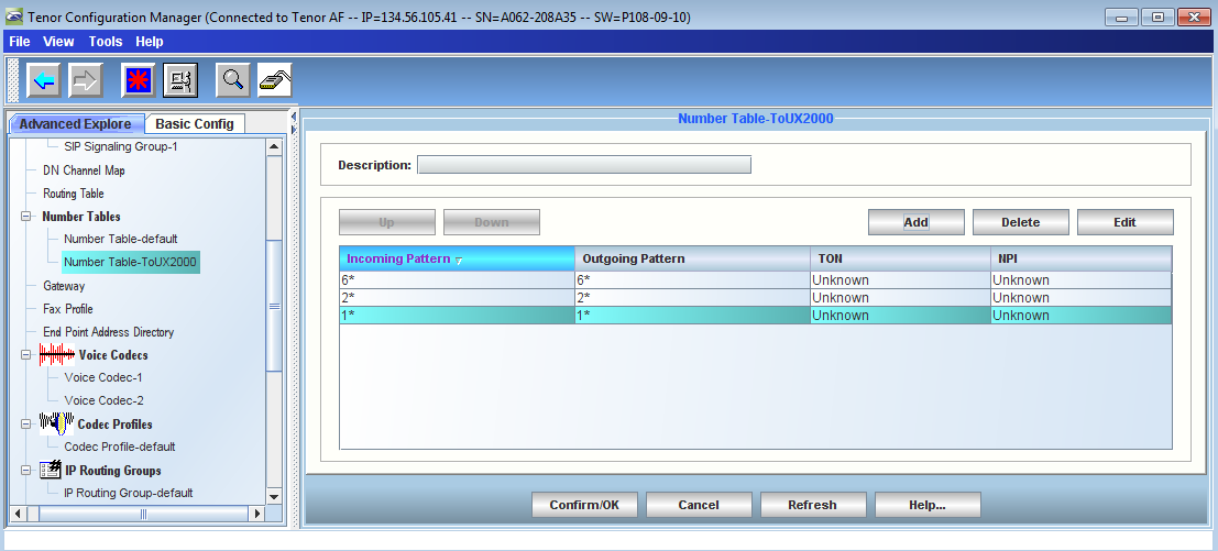
- Create a new Number Tables to allow Analog Endpoints to be able to make calls to LYNC endpoints as wells as to PBX endpoints as shown below
| Panel |
|---|
|
| Caption |
|---|
| 0 | Figure |
|---|
| 1 | Enter Number Table Information |
|---|
| 
|
|
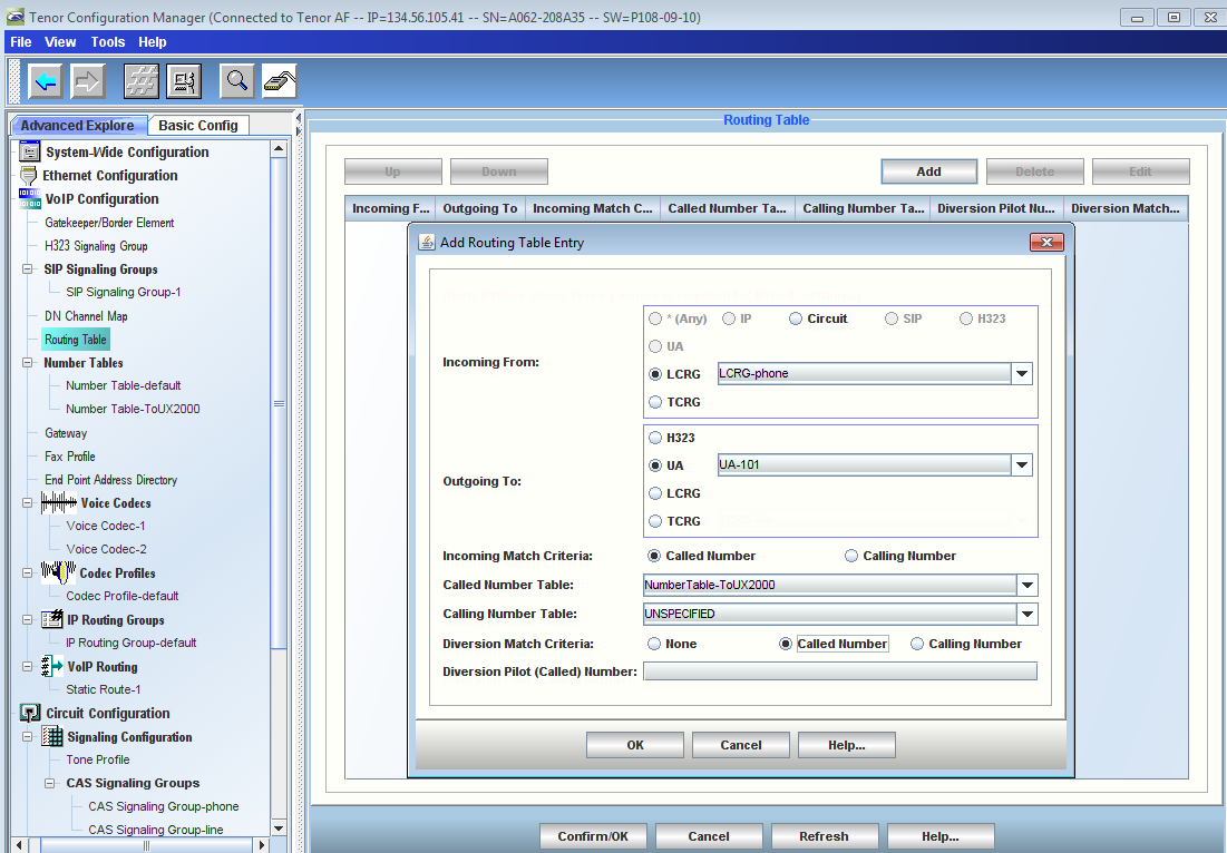
- Create an entry in the Routing Table as shown below
| Panel |
|---|
|
| Caption |
|---|
| 0 | Figure |
|---|
| 1 | Routing Table Entry |
|---|
| 
|
|
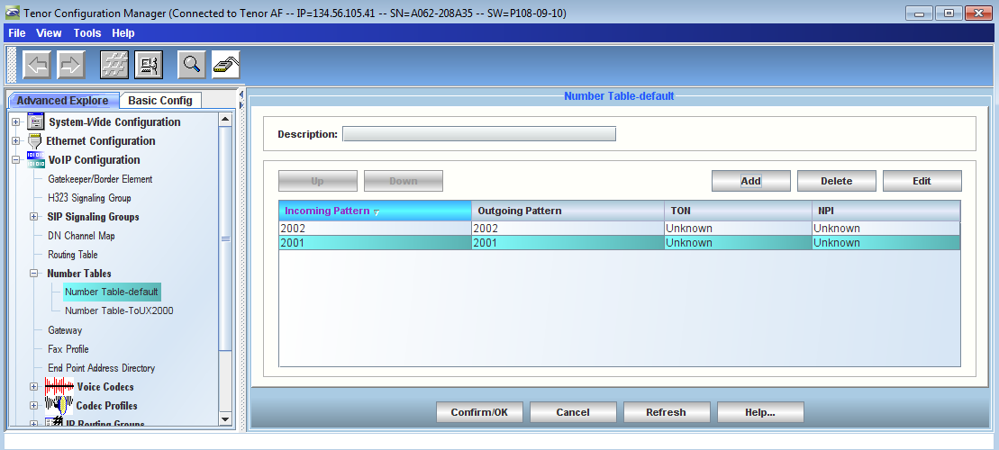
- Modify the default Number Table to allow incoming calls to Tenor Device as shown below
| Panel |
|---|
|
| Caption |
|---|
| 0 | Figure |
|---|
| 1 | Modify Default Number Table |
|---|
| 
|
|
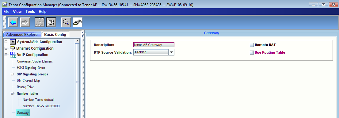
- Verify that "Use Routing Table" option is selected in Gateway configuration field as shown below
| Panel |
|---|
|
| Caption |
|---|
| 0 | Figure |
|---|
| 1 | Select Use Routing Table |
|---|
| 
|
|
Verifying Codec Selection
| Info |
|---|
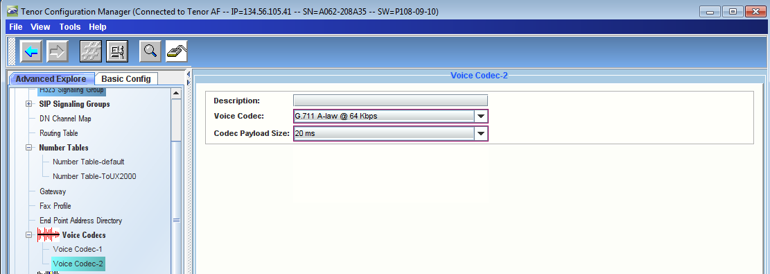
Ensure that the codec settings are identical with the matching codec inSBC.
Use only G.711U and/or G.711A. |
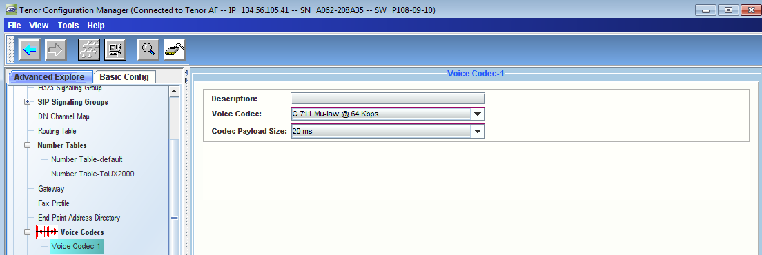
- Verify that Voice Codec settings are configured correctly as shown below
| Panel |
|---|
|
| Caption |
|---|
| 0 | Figure |
|---|
| 1 | Verify Voice Codec - 1 |
|---|
| 
|
|
| Panel |
|---|
|
| Caption |
|---|
| 0 | Figure |
|---|
| 1 | Verify Voice Codec - 2 |
|---|
| 
|
|
Verify Supplementary Services Enabled
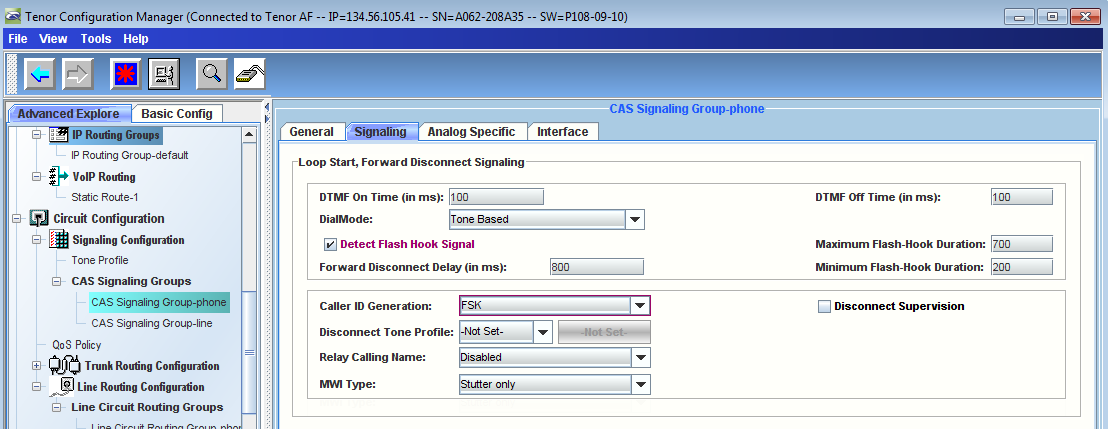
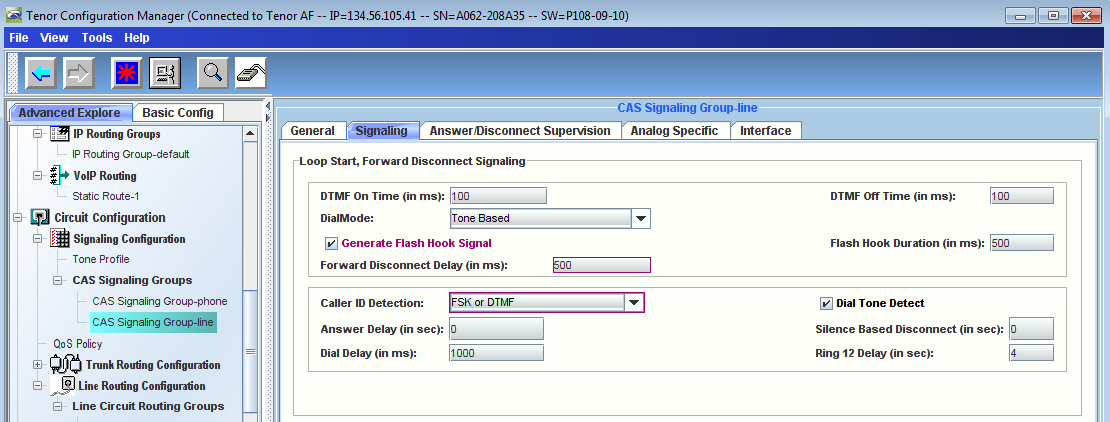
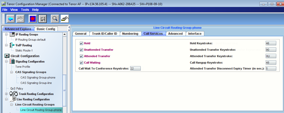
Tenor supports the following supplementary services - Hold/Unhold, Unattended (Blind) Transfer, and Attended (Consultative) Transfer. These features can be enabled and configured using either a Line Circuit Routing Group (LCRG) or Trunk Circuit Routing Group (TCRG). Follow the configuration steps below:
- Verify that "Detect Flash Hook Signal" option is selected in CAS Signaling Group-phone > Signaling Tab
| Panel |
|---|
|
| Caption |
|---|
| 0 | Figure |
|---|
| 1 | Select Detect Flash Hook Signal |
|---|
| 
|
|
- Verify that "Generate Flash Hook Signal" option is selected in CAS Signaling Group-line > Signaling Tab
| Panel |
|---|
|
| Caption |
|---|
| 0 | Figure |
|---|
| 1 | Select Generate Flash Hook Signal |
|---|
| 
|
|
- Verify that Call Services are selected in Line Circuit Routing Group-phone > Call Services Tab
| Panel |
|---|
|
| Caption |
|---|
| 0 | Figure |
|---|
| 1 | Select Call Services |
|---|
| 
|
|
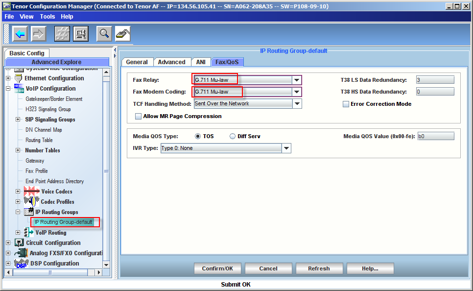
Change Change Fax Relay from T.38 without Fallback to G.711
| Panel |
|---|
|
| Caption |
|---|
| 
|
|
Configuring the Relay of Calling Name (CNAM)
The configuration of the Calling Name (CNAM) is optional. Tenor can relay CNAM in both directions Analog to SIP and SIP to Analog.
| Div |
|---|
|
| Caption |
|---|
| 0 | Table |
|---|
| 1 | Relay of Calling Name |
|---|
| | Analog to SIP | SIP to Analog |
|---|
Not send CNAM | VoIP Configuration > IP Routing Groups > IP Routing Group-default > ANI > Relay Calling Name - Disabled
 Image Modified Image Modified
| Circuit Configuration > Signaling Config > CAS Signaling Groups > CAS Signaling Group-phone > Relay Calling name - Disabled
 Image Modified Image Modified
|
|---|
Send the CNAM | Send the CNAM of each analog line as configured in the DN Channel Map: - First add the Calling Name in the channel mapping for each channel.
VoIP Configuration > DN Channel Map > Calling Name - Free text
 Image Modified Image Modified - Secondly select the global default behavior.
VoIP Configuration > IP Routing Group > IP Routing Group-default > ANI > Relay Calling name - Relay CNAM in INVITE
 Image Modified Image Modified
| Send the CNAM from the SIP call leg.
Circuit Configuration > Signaling Config > CAS Signaling Groups > CAS Signaling Group-phone > Signaling > Relay Calling Name - Relay CNAM
 Image Modified Image Modified |
|---|
Send default CNAM | Send a default CNAM for all calls regardless of the Calling Name of the originating channel.
VoIP Configuration > IP Routing Group > IP Routing Group-default > ANI > Relay Calling name > Relay Default CNAM > Default Calling Name - Free text
 Image Modified Image Modified | Send a default CNAM for all calls regardless of the Calling Name of the originating channel.
Circuit Configuration > Signaling Config > CAS Signaling Groups > CAS Signaling Group-phone > Signaling > Relay Calling Name > Relay Default CNAM > Default Calling Name - Free text
 Image Modified Image Modified |
|---|
|
|
Sample Tenor AF Configuration File
expand- P108-09-10
here the Tenor AF DB file Software
|
Version | Cloak |
|---|
| title | Click here to see the Tenor AF DB file Software Version P108to read more... |
|---|
|
| none |
Sample Tenor AF Configuration File - P107-09-10
| Noprint |
|---|
Click to see Tenor AF DB file Software version P107-09-10...
|
| Cloak |
|---|
| title | Click to read more... |
|---|
|
| none |
| Code Block |
|---|
none | none | # /*<-- System Info. Do not overwrite!
# Product: Tenor AF
# IP: 134.56.105.41
# Subnet: 255.255.255.0
# Gateway: 134.56.105.1
# Software: P108-09-10
# Serial Number: A062-208A35
# DB: DB_CMS_M15_A019_V13.0.0_080109
# Updated: WED JUN 22 22:56:23 2011
# -->*/
config
table off
VOIPNetwork 1
SIte 1
TimeServer 1
set UTCOffset 0:00
set PrimaryServerIPAddr 134.56.113.11
set SecondaryServerIPAddr 128.138.140.44
DialPlan 1
set MAXDNlength 30
set MINDNlength 1
set LongDistancePrefix ""
set CarrierPrefixPattern ""
set INTernationaLPrefix[1] ""
set DialPlanCountry 255
UserProgramDialPlan 1
PRIVateNumberingPlan 1
MasterChassis 1
set Type 6
set DBVersion "DB_CMS_M15_A019_V13.0.0_080109"
set SNMPTrapCommunity "trap community"
IVRFileServer 1
SYSLogServer 1
set id "1"
CDRServer 1
set id "1"
CDRServer 2
set id "2"
set CDRServerPort 9003
new ChannelGroup phone
ChannelGroup phone
new ChannelGroup line
ChannelGroup line
NMSServer 1
DNSHosts 1
DNSServer 1
set UseConfiguredDNSServers 1
set PrimaryServerIPAddr 172.16.250.30
set SecondaryServerIPAddr 134.56.112.12
RadiusInfo UserServer
set name "User Authentication Server"
RadiusInfo EndpointServer
set name "Endpoint Authorization Server"
RadiusInfo RoutingServer
set name "External Routing Server"
DOMain 1
set Company "Quintum"
ZOne 1
GateWay 1
set Description "Tenor AF Gateway"
set OutgoingIPRouting 1
set UseRoutingTable 1
VoiceCodec 1
set name ""
set CodecVoiceCoding 9
set CodecPayloadSize 20
set ucVar2 0
VoiceCodec 2
set name ""
set CodecVoiceCoding 8
set CodecPayloadSize 20
set ucVar2 0
CodecProfile default
CASSignalingGroup phone
set id "phone"
set SignalingType 3
set FlashhookSignal 1
set ForwardDisconnectDelay 800
set CallerIDGeneration 1
set RXGain -6
set TXGain 0
CASSignalingGroup line
set id "line"
set ORientation 0
set SignalingType 3
set FlashhookSignal 1
set ForwardDisconnectDelay 500
set CallerIDDetection 1
set RXGain 6
set TXGain 0
SIPSignalingGroup 1
set PrimarySIPServer "172.16.250.246"
set AllowOnlyProxyCalls 0
set SipPstnInterworking 1
set UserAgentHeader "Quintum/1.0.0"
change 1 lp 5060
add 5061 ua 102 pu 2001 ppw 2001 c[1] 2001
add 5062 ua 103 pu 2002 ppw 2002 c[1] 2002
H323SignalingGroup 1
TrunkCircuitRoutingGroup line
set id "line"
set EndOfDialDigit #
LineCircuitRoutingGroup phone
set id "phone"
set EndOfDialDigit #
set CallWaiting 1
set HolD 1
set UnattendedTRansfer 1
set AttendedTRansfer 1
FaxProfile 1
set FaxNominalDelay 200
IPRoutingGroup default
set EndOfDialDigit #
set MediaQOSValue b0
set SignalingQOSValue b0
ToneProfile 1
set id "1"
DNChannelMap 1
add 2001 ua 102
add 2002 ch 2 ua 103
NumberTable default
set id "default"
add 2001 op 2001
add 2002 op 2002
new NumberTable ToSBC
NumberTable ToSBC
set id "ToSBC"
add 1* op 1*
add 2* op 2*
add 6* op 6*
RoutingTable 1
add LCRG-phone ot UA-101 cdnt NT-ToSBC dmc cd
GateKeeperParam 1
EndPointAddressDirectory 1
QOSPolicy 1
RouteDirectory 1
StaticRoute 1
set id "1"
table on
ChannelGroup phone
set SignalingGroupAttached CASSignalingGroup-phone
set RoutingGroupAttached LineCircuitRoutingGroup-phone
ChannelGroup line
set SignalingGroupAttached CASSignalingGroup-line
set RoutingGroupAttached TrunkCircuitRoutingGroup-line
CodecProfile default
set VoiceCodecAttached[1] VoiceCodec-1
set VoiceCodecAttached[2] VoiceCodec-2
TrunkCircuitRoutingGroup line
LineCircuitRoutingGroup phone
IPRoutingGroup default
set CodecProfileAttached CodecProfile-default
StaticRoute 1
set IPRoutingGroupAttached IPRoutingGroup-default
# DO NOT TOUCH: Integrity Checked!
|
| Expand |
|---|
| Click here to see the Tenor AF DB file Software Version P107-09-10 | Click here to see the Tenor AF DB file Software Version P107-09-10 | | Code Block |
|---|
| none | none | # /*<-- System Info. Do not overwrite!
# Product: Tenor AF
# IP: 10.0.0.164
# Subnet: 255.255.255.0
# Gateway: 10.0.0.1
# Software: P107-09-10
# Serial Number: A062-999999
# DB: DB_CMS_M14_A018_V12.0.0_121107
# Updated: SAT JUN 25 20:32:46 2011
# -->*/
config
table off
VOIPNetwork 1
SIte 1
TimeServer 1
set UTCOffset 0:00
set PrimaryServerIPAddr 10.0.0.10
set SecondaryServerIPAddr 10.0.2.10
DialPlan 1
set MAXDNlength 30
set MINDNlength 1
set LongDistancePrefix ""
set CarrierPrefixPattern ""
set INTernationaLPrefix[1] ""
set DialPlanCountry 255
set ProgressToneCountry 6
UserProgramDialPlan 1
IPDialPlan default
PRIVateNumberingPlan 1
MasterChassis 1
set Type 6
set DBVersion "DB_CMS_M14_A018_V12.0.0_121107"
set SNMPTrapCommunity "trap community"
IVRFileServer 1
SYSLogServer 1
set id "1"
CDRServer 1
set id "1"
CDRServer 2
set id "2"
set CDRServerPort 9003
new ChannelGroup phone
ChannelGroup phone
NMSServer 1
DNSHosts 1
DNSServer 1
set PrimaryServerIPAddr 10.0.0.10
set SecondaryServerIPAddr 10.0.2.10
RadiusInfo UserServer
set name "User Authentication Server"
RadiusInfo EndpointServer
set name "Endpoint Authorization Server"
RadiusInfo RoutingServer
set name "External Routing Server"
DOMain 1
set Company "Quintum"
ZOne 1
GateWay 1
set Description "Tenor AF Gateway"
set OutgoingIPRouting 1
NumberDirectories 1
BypassNumberDirectory 1
set id "1"
HuntLDNDirectory pub1
set id "pub1"
HuntLDNDirectory prv1
set id "prv1"
set LDNType 1
CallerIDXlationDirectory 1
set id "1"
InboundDNISXlationDirectory 1
set id "1"
HopoffNumberDirectory 1
set id "1"
VoiceCodec 1
set name "G711A"
set CodecVoiceCoding 8
set CodecPayloadSize 20
set ucVar2 0
VoiceCodec 2
set name "G711U"
set CodecVoiceCoding 9
set CodecPayloadSize 20
set ucVar2 0
CodecProfile default
CASSignalingGroup phone
set id "phone"
set SignalingType 3
set ForwardDisconnectDelay 800
set CallerIDGeneration 1
set RXGain -6
set TXGain 0
CASSignalingGroup line
set id "line"
set ORientation 0
set ForwardDisconnectDelay 500
set RXGain 6
set TXGain 0
SIPSignalingGroup 1
set PrimarySIPServer "172.23.197.30"
set AllowOnlyProxyCalls 0
set UserAgentHeader "Quintum/1.0.0"
change 1 lp 5060 pu 200829 ppw 200829 c[1] 200829
add 5061 ua 102 pu 200827 ppw 200827 c[1] 200827
H323SignalingGroup 1
TrunkCircuitRoutingGroup line
set id "line"
set EndOfDialDigit #
LineCircuitRoutingGroup phone
set id "phone"
set EndOfDialDigit #
set ModemBypass 1
FaxProfile 1
set FaxNominalDelay 200
IPRoutingGroup default
set EndOfDialDigit #
set MediaQOSValue b0
set FaxRelay 3
set SignalingQOSValue b0
ToneProfile 1
set id "1"
DNChannelMap 1
add 200829 ua 101
add 200827 ch 2 ua 102
GateKeeperParam 1
EndPointAddressDirectory 1
QOSPolicy 1
RouteDirectory 1
StaticRoute 1
set id "1"
table on
ChannelGroup phone
set SignalingGroupAttached CASSignalingGroup-phone
set RoutingGroupAttached LineCircuitRoutingGroup-phone
CodecProfile default
set VoiceCodecAttached[1] VoiceCodec-1
set VoiceCodecAttached[2] VoiceCodec-2
TrunkCircuitRoutingGroup line
set HopoffNumberDirAttached[1] HopoffNumberDirectory-1
LineCircuitRoutingGroup phone
set BypassNumberDirAttached[1] BypassNumberDirectory-1
set PUBHuntLdnDirAttached[1] HuntLDNDirectory-pub1
set PRIVHuntLdnDirAttached[1] HuntLDNDirectory-prv1
IPRoutingGroup default
set CodecProfileAttached CodecProfile-default
set IPDialPlanAttached IPDialPlan-default
StaticRoute 1
set IPRoutingGroupAttached IPRoutingGroup-default
# DO NOT TOUCH: Integrity Checked!
Ribbon SBC 1000/2000 configuration
Requirements and Prerequisites
- This document assumes thatSBC Lync 2010 wizard was ran prior to the configuration
- Running the Lync 2010 wizard will ensure SRTP towards Lync is set to Required
- Media bypass must be enabled in Lync
SIP Registrar Table
- Browse toSBC 2000 WebUI > Settings Tab > SIP / Local Registrars (in left pane)
- Click on Add
 button and add a SIP Local Registrar Entry as shown below
| Panel |
|---|
|
| Caption |
|---|
| 0 | Figure |
|---|
| 1 | Add SIP Local Registrar Entry |
|---|
| 
|
|
- Browse toSBC 2000 WebUI > Settings Tab > Media List (in left pane)
- Click on Add
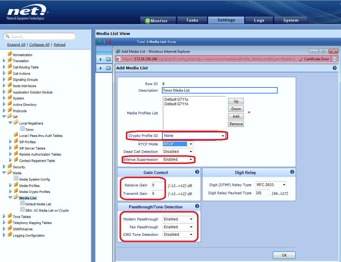
 button and add a Media List Entry as shown below
Make sure to have following settings are configured in Tenor Media List:
| |
| Background Color |
|---|
| | Fax passthru |
| |
| Background Color |
|---|
| | Modem Passthru |
| |
| Background Color |
|---|
| | Silence Suppression |
| |
| Background Color |
|---|
| | Rx/Tx Gain |
| |
| Panel |
|---|
|
| Caption |
|---|
| 
|
|
Translation Table
- Browse toSBC 2000 WebUI > Settings Tab > Translation (in left pane)
- Click on Add
 button and add a Translation Table with following entry as shown below
| Panel |
|---|
|
| Caption |
|---|
| 0 | Figure |
|---|
| 1 | Add Translation Table |
|---|
| 
|
|
Signaling Group (uses UDP only)
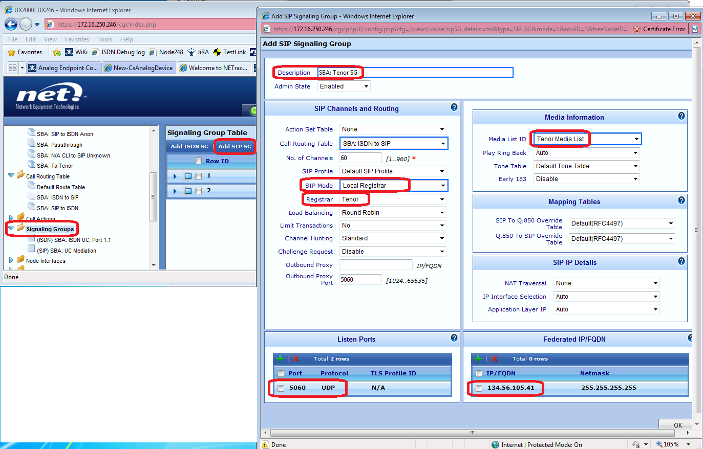
- Browse toSBC 2000 WebUI > Settings Tab > Signaling Groups (in left pane)
- Click on Add SIP SG button and add a SIP Signaling Group for Tenor Device connectivity as shown below
| Panel |
|---|
|
| Caption |
|---|
| 0 | Figure |
|---|
| 1 | Add SIP Signaling Group |
|---|
| 
|
|
Call Routing Table
- Browse toSBC 2000 WebUI > Settings Tab > Call Routing Table (in left pane)
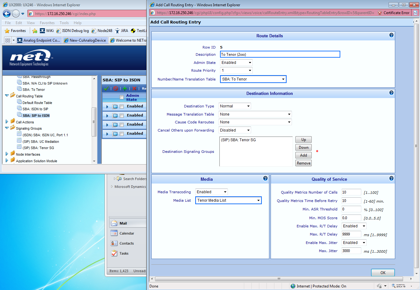
- Click on SIP to ISDN Call Route Table and hit Add
 button to add an entry to route calls to Tenor (for those with 2xxx extension in this example)
| Panel |
|---|
|
| Caption |
|---|
| 0 | Figure |
|---|
| 1 | Add Entry to Route Calls |
|---|
| 
|
|
- Re-sequence the Call Route entries in this table to make sure that calls to 2xxx extensions (Analog Endpoints) will use the entry that you just created in previous step
| Panel |
|---|
|
| Caption |
|---|
| 0 | Figure |
|---|
| 1 | Re-sequence Call Route Entry |
|---|
| 
|
|
Troubleshooting Techniques
Troubleshooting FAX Calls Between the Tenor and PSTN
Before running the commands above, make sure that the relevant Organizational Unit(OU) (in this example it is named Analog) exists in Active Directory. On a machine that can access the Active Directory Users and Computers snap-in, launch the Active Directory Users and Computers snap-in and verify that OU is present as shown in below screenshot:
button and add a SIP Local Registrar Entry as shown below
button and add a Media List Entry as shown below
button and add a Translation Table with following entry as shown below
button to add an entry to route calls to Tenor (for those with 2xxx extension in this example)


